Supercharge Your Innovation With Domain-Expert AI Agents!

Gas turbine engine

A technology of gas turbines and gas turbines, which is applied in the direction of gas turbine devices, machines/engines, non-variable engines, etc., can solve the problems of bulky, long gas turbine engines, etc., and achieve high efficiency, low internal power loss, and improved efficiency Effect

Pending Publication Date: 2022-06-21
TNS TECH
View PDF0 Cites 0 Cited by
  • Summary
  • Abstract
  • Description
  • Claims
  • Application Information

AI Technical Summary

Problems solved by technology

Conventional gas turbine engines tend to be long and heavy due to the fact that the various stages of the gas turbine engine are usually arranged along a common shaft

Method used


Image

  • Gas turbine engine
  • Gas turbine engine
  • Gas turbine engine

Examples


Embodiment Construction

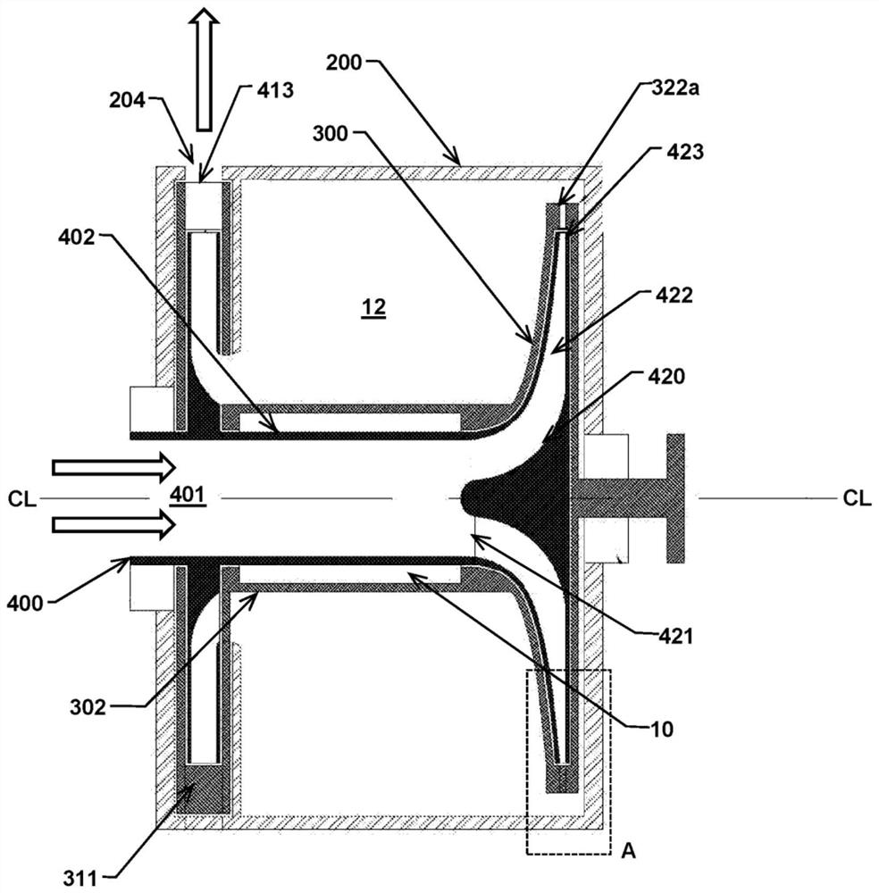
[0022] The following description may use terms such as "horizontal", "vertical", "lateral", "front and rear", "upper and lower", "upper", "lower", "inner", "outer", "inward" forward", "backward", etc. These terms generally refer to the view and orientation as shown in the drawings and are associated with normal use of the invention. The terminology is for the convenience of the reader only and should not be limiting.

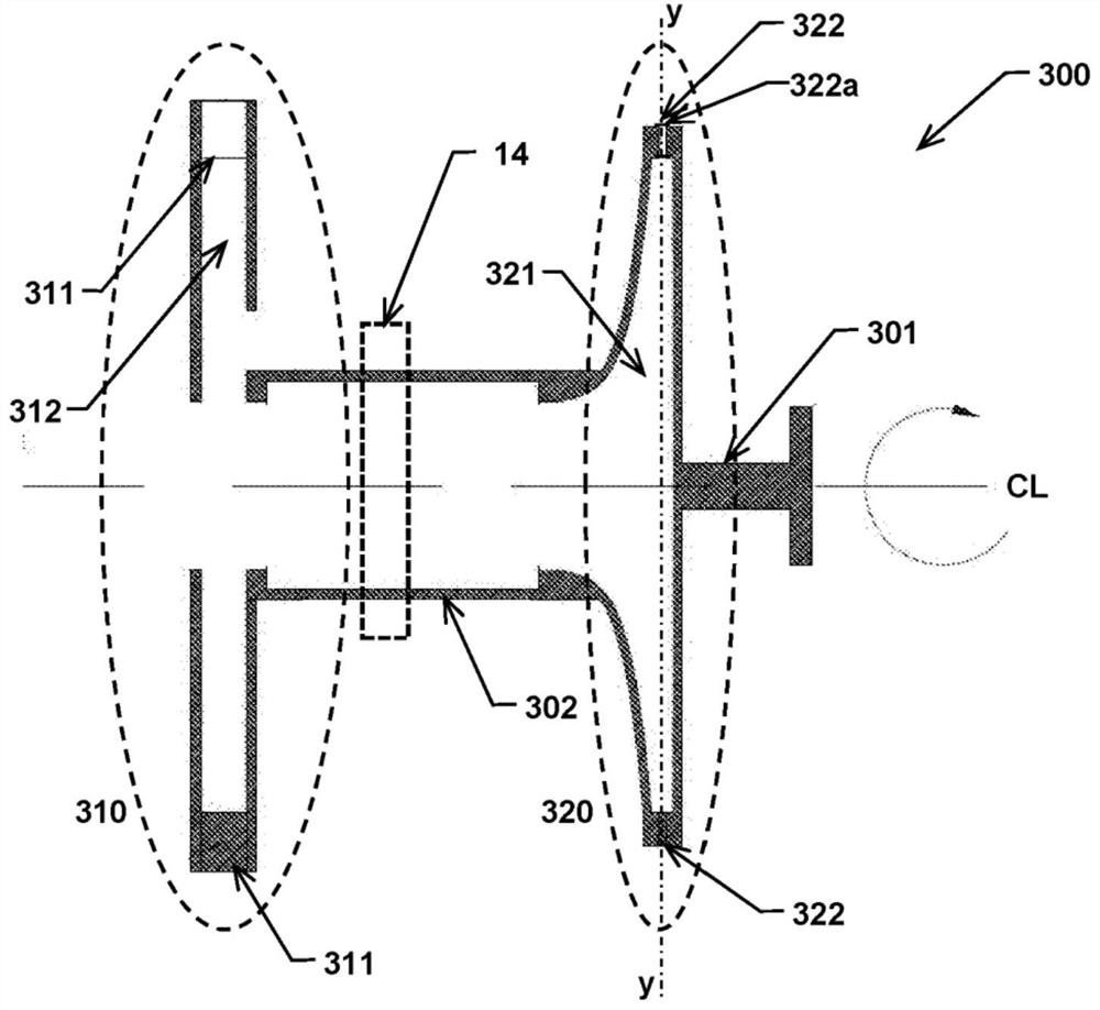
[0023] First refer to figure 1 , a gas turbine engine according to the present invention generally comprises the following three units nested within each other and arranged around a common axis of rotation CL: a power output turbine unit (POT) 300 rotatably arranged inside the outer casing unit 200 and a rotatable A compressor turbine unit (CTU) 400 is arranged in rotation inside the POT 300 . In the following, the compressor turbo unit (CTU) is also referred to as the first turbo unit 400 and the power output turbo unit (POT) is also referred to as the secon...


PUM


Abstract

A gas turbine engine comprises at least a power output turbine unit (POT) (300) and a compressor turbine unit (CTU) (400), the POT being rotatably arranged inside an outer casing unit (200), the CTU being rotatably arranged inside the POT (300), and the CTU, POT and outer casing unit being arranged about a common axis of rotation (CL). The POT (300) and the CTU (400) are arranged at a close distance (d) such that a kinetic friction coupling is created between the POT (300) and the CTU (400).

Description

technical field [0001] The present invention relates to the field of gas turbines, and more particularly to a gas turbine as specified by the preamble of claim 1 . Background technique [0002] A gas turbine engine, in its most basic form, consists of a rotating gas compressor in which a gas, such as air, is compressed, a combustor, and a downstream turbine, and in the combustor, fuel is added to the compressed air Mid-fired to produce high velocity exhaust gas, a downstream turbine is coaxial with the gas compressor and configured to rotate through the exhaust gas. The shaft is usually connected to the turbine, whereby the gas turbine engine can be used to drive propellers, generators or other applied components. [0003] Air and other gases flowing through a gas turbine engine cause skin frictional drag and irreversible turbulence. These factors result in a reduction in engine efficiency, which is the ratio of work actually output to the net input energy supplied in the ...

Claims


Application Information

Patent Timeline
Patent Type & Authority Applications(China)
IPC IPC(8): F02C3/10F02C3/14F02C3/073F02C7/36
CPCF02C3/14F02C3/10F02C3/073F01D1/22F02C3/103F02C3/085F02C3/05F02C7/36
Inventor 托莱克·斯唐厄兰
Owner TNS TECH
Features
  • R&D
  • Intellectual Property
  • Life Sciences
  • Materials
  • Tech Scout
  • Unparalleled Data Quality
  • Higher Quality Content
  • 60% Fewer Hallucinations
Learn More