Starting circuit for integrated circuit of power factor correction controller

A power factor correction and startup circuit technology, which is applied to output power conversion devices, electric light sources, electrical components, etc., can solve the problems of sacrificing system startup time, startup resistance R1 consumption, high power, etc., to reduce startup time, The effect of eliminating power loss and improving system efficiency

Inactive Publication Date: 2010-03-31
OSRAM GMBH
View PDF2 Cites 6 Cited by
  • Summary
  • Abstract
  • Description
  • Claims
  • Application Information

AI Technical Summary

Problems solved by technology

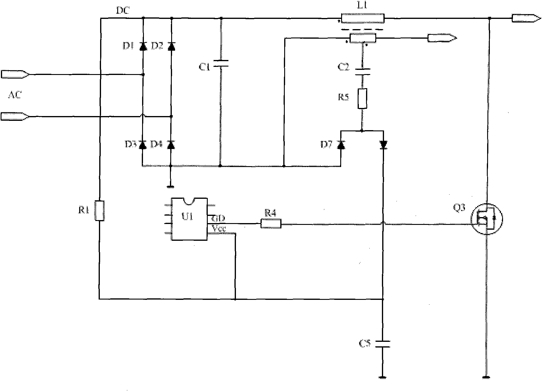
[0004] The disadvantage of the above circuit is that after the charge pump circuit starts to work, the starting resistor R1 consumes a large amount of power
Although the resistance value can be increased to reduce the power loss, the start-up time of the system is sacrificed because the increased resistance simultaneously reduces the current flowing through the start-up resistor during start-up

Method used


Image

  • Starting circuit for integrated circuit of power factor correction controller
  • Starting circuit for integrated circuit of power factor correction controller
  • Starting circuit for integrated circuit of power factor correction controller

Examples


Embodiment Construction

[0013] Exemplary embodiments of the present invention will be described below with reference to the accompanying drawings. In the interest of clarity and conciseness, not all features of an actual implementation are described in this specification. However, it should be understood that many implementation-specific decisions must be made in developing any such practical implementation in order to achieve the developer's specific goals, and that these decisions may vary from implementation to implementation . Moreover, it should also be understood that development work, while potentially complex and time-consuming, would at least be a routine undertaking for those skilled in the art having the benefit of this disclosure.

[0014] Here, it should also be noted that, in order to avoid obscuring the present invention due to unnecessary details, only the device structure closely related to the solution according to the present invention is shown in the drawings, and the relationshi...


PUM


Abstract

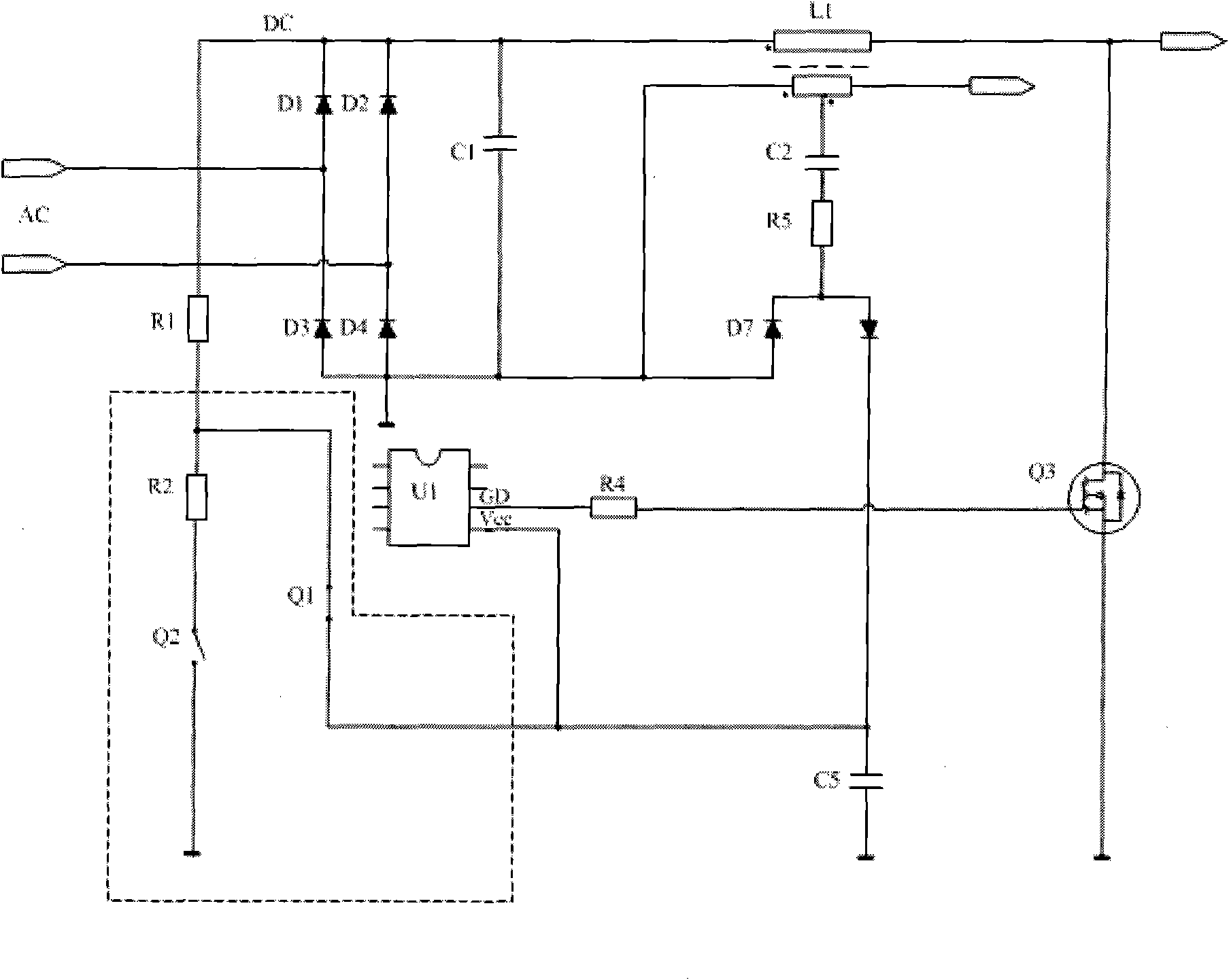
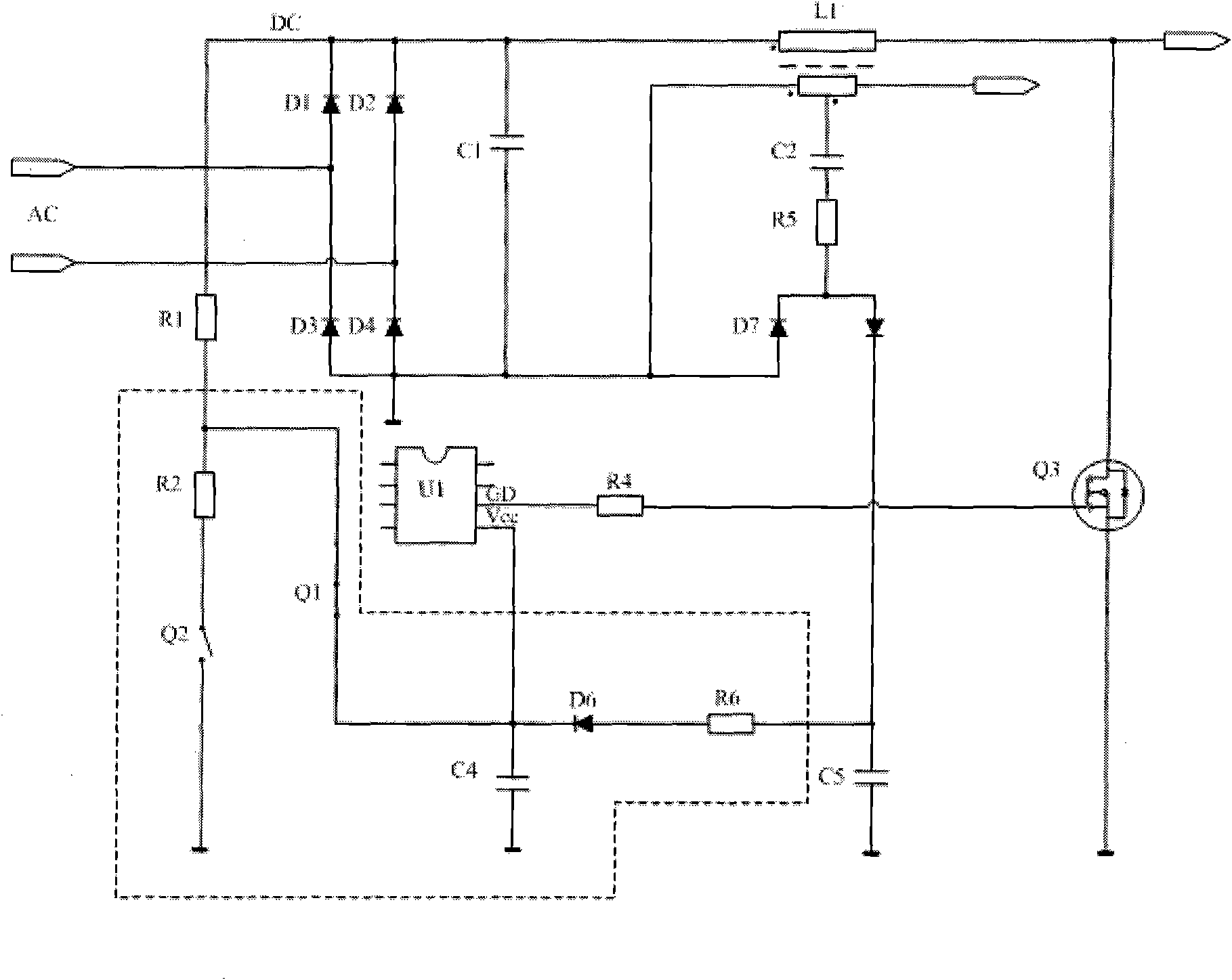
The invention provides a starting circuit for an integrated circuit of a power factor correction control chip, which comprises a rectification circuit and a charge pump circuit, wherein the output ofthe rectification circuit is connected to a power supply pin of the chip by a starting resistor; and the output end of the charge pump circuit is connected with the power supply pin of the chip. The starting circuit comprises a first current path and a second current path, wherein the input end of the first current path is connected with the starting resistor, and the output end of the first current path is connected with the power supply pin of the chip; the input end of the second current path is connected with the starting resistor, and the output end of the second current path is connectedwith the earth potential; when the power is switched on, the first current path is switched on, and the second current path is switched off; and when the power factor correction control chip operatesnormally, the first current path is switched off, and the second current path is switched on.

Description

technical field [0001] The invention relates to a starting circuit, in particular to a starting circuit applied to a power factor correction (PFC) controller integrated circuit (IC). Background technique [0002] Typically, the PFC controller IC takes its supply current from a charge pump circuit connected to the boost inductor's auxiliary winding. However, no high-frequency current flows through the boost inductor until the IC is powered up. To start an IC, the usual solution is to connect a start-up resistor between the direct current (DC) rail and the supply pin of the IC. Since most of the blocks in the IC have not yet started to work during the start-up phase, the current required to activate the IC is usually less than 1mA. Depending on the rectified DC rail voltage, the value of the startup resistor is typically on the order of hundreds of kilohms. [0003] figure 1 A prior art start-up circuit is shown. The start-up circuit includes a rectifier circuit composed ...

Claims


Application Information

Patent Timeline
Patent Type & Authority Applications(China)
IPC IPC(8): H02M1/42H05B41/14
CPCH02M2001/0006H02M1/36Y02B70/126H05B41/2824Y02B20/186H02M1/4225Y02B20/00Y02B70/10H02M1/0006H05B41/282
Inventor 李尚斌马昌松
Owner OSRAM GMBH
Why Eureka
Try Eureka