Eureka AIR delivers breakthrough ideas for toughest innovation challenges, trusted by R&D personnel around the world.

Rotational flow device, flocculator containing rotational flow device and application of flocculator

The technology of a cyclone device and a flocculator, which is applied in the field of water treatment equipment, can solve the problems of low construction efficiency, cumbersome disassembly and assembly, low water treatment capacity, etc., and achieve the effects of easy mass production, simple operation and reduced impact.

Pending Publication Date: 2022-06-24
北京中环达生态科技有限公司
View PDF10 Cites 0 Cited by
  • Summary
  • Abstract
  • Description
  • Claims
  • Application Information

AI Technical Summary

Problems solved by technology

[0004] The patent document with application number 202110023113.3 discloses a spiral micro-vortex flocculator. Since the flocculators are fixed with iron wires, it is necessary to manually cross the thin steel wires across the flocs, and then connect them in series. The assembly and installation are very cumbersome and the construction Low efficiency, disassembly and assembly are cumbersome, and long-term use will easily lead to deformation of the overall layout of the flocculator, and the flocculation effect cannot be guaranteed
[0005] The patent document with the application number 202110480068.4 discloses a modular reaction flocculator for water treatment and its production method. The working principle of the above-mentioned flocculator is to rely on the thread on the inner wall of the flocculator to disturb the water flow. Since the inner wall of the flocculator The thread on the top of the flocculator is shallow and cannot make the water flow form a large swirl, so the flocculator has the problems of low water treatment capacity and poor flocculation effect

Method used


Image

  • Rotational flow device, flocculator containing rotational flow device and application of flocculator
  • Rotational flow device, flocculator containing rotational flow device and application of flocculator
  • Rotational flow device, flocculator containing rotational flow device and application of flocculator

Examples


Embodiment

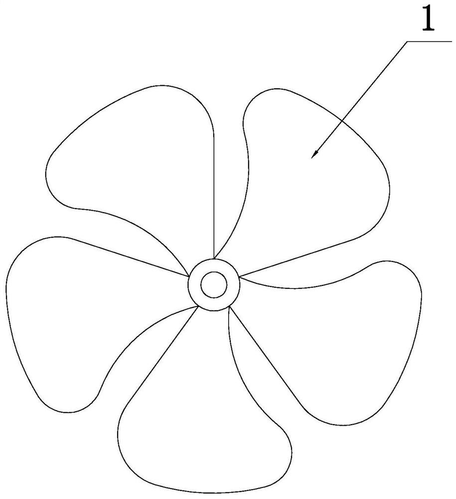
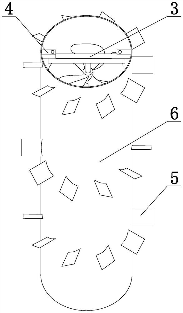
[0054] The swirl device includes a blade main shaft 2 and a blade 1, and the blade 1 is arranged on the blade main shaft 2 at intervals along the axial direction and is distributed along the radial direction; it is characterized in that the blade 1 adopts the shape of a fan blade, and also includes a The cylinder 6 on the outside of the blade 1, the top of the cylinder 6 is open, the lower side wall of the cylinder 6 is provided with a water inlet pipe 11 that communicates with its inner cavity, the top and bottom ends of the main shaft 2 of the blade are fixed with the cylinder 6, and the outer wall of the cylinder 6 is The fin sloping plate 5 is fixed at intervals, and the included angle between the fin sloping plate 5 and the horizontal plane is α, 45°≤α≤60°.

[0055] The cylinder body 6 is connected with the top of the blade main shaft 2 through the fixing rod 3, the fixing block 4 and the bolts.

[0056] The blades 1 distributed in the same radial direction and the blades...


PUM


Abstract

The invention belongs to water treatment equipment, and particularly relates to a rotational flow device, a flocculator containing the rotational flow device and application of the flocculator. The rotational flow device comprises a paddle main shaft and paddles, and the paddles are arranged on the paddle main shaft at intervals in the axial direction and distributed in the radial direction; the top of the barrel body is open, the side wall of the lower part of the barrel body is provided with a water inlet pipe communicated with an inner cavity of the barrel body, the top end and the bottom end of a main shaft of the paddle are fixed with the barrel body, wing panel inclined plates are fixed on the outer wall of the barrel body at intervals, and the included angle alpha between each wing panel inclined plate and the horizontal plane is more than or equal to 45 degrees and less than or equal to 60 degrees. The problems of complicated installation, poor flocculation effect and the like in the prior art are solved. The device has the advantages of good flocculation effect, convenience in installation and the like.

Description

technical field [0001] The invention belongs to water treatment equipment, in particular to a cyclone device, a flocculator containing the cyclone device and its application. Background technique [0002] Flocculation and sedimentation is a very important process step in the conventional water treatment process. Its flocculation effect directly affects the effect of water treatment. The completion of the flocculation and sedimentation process requires two conditions: chemical and hydraulic: the chemical condition is to add flocculant to the raw water. The suspended small particles and colloidal substances are destabilized to form small flocs; the hydraulic condition is to form a suitable flow velocity distribution by restricting the water flow, and the small flocs collide with each other in the water flow, cohesion, adsorption and flocculation, and form more solid large flocs. The large flocs sink under the action of gravity, and finally achieve the effect of solid-liquid se...

Claims


Application Information

Patent Timeline
Patent Type & Authority Applications(China)
IPC IPC(8): B01F27/191B01F27/90B01F33/81C02F1/52
CPCC02F1/52C02F2201/002
Inventor 吴江渤程丽李乐乐李风文袁云飞焦政统丁昕冉刘海源辛小民
Owner 北京中环达生态科技有限公司
Why Eureka
Eureka Blog
Learn More