
Grinding device driven by auxiliary grinding roller

A grinding roller and grinding technology, applied in the field of vertical roller grinding equipment, can solve the problems of stable and reliable operation of unfavorable equipment, low working pressure of auxiliary grinding rollers, and large fluctuation of material layer thickness, so as to optimize material supply and improve grinding efficiency. , Improve the efficiency of grinding

Pending Publication Date: 2022-06-24
中材(天津)粉体技术装备有限公司 +1
View PDF0 Cites 1 Cited by
  • Summary
  • Abstract
  • Description
  • Claims
  • Application Information

AI Technical Summary

Problems solved by technology

During the operation of the mill, there is high-frequency vibration, and the friction force of the grinding material on the auxiliary grinding roller is momentarily small; in addition, the working pressure of the auxiliary grinding roller is low, especially when the friction coefficient of the material is small, the friction of the material driving the auxiliary grinding roller to rotate The force is too small; the linear velocity at the middle diameter of the auxiliary grinding roller is lower than that at the corresponding grinding disc position, and there is a problem that the speed difference is too large, resulting in the accumulation of materials in front of the auxiliary grinding roller, and there are large fluctuations in the thickness of the material layer and grinding. The problem of large machine vibration is not conducive to the stable and reliable operation of the equipment

Method used


Image

  • Grinding device driven by auxiliary grinding roller
  • Grinding device driven by auxiliary grinding roller
  • Grinding device driven by auxiliary grinding roller

Examples


Embodiment 1

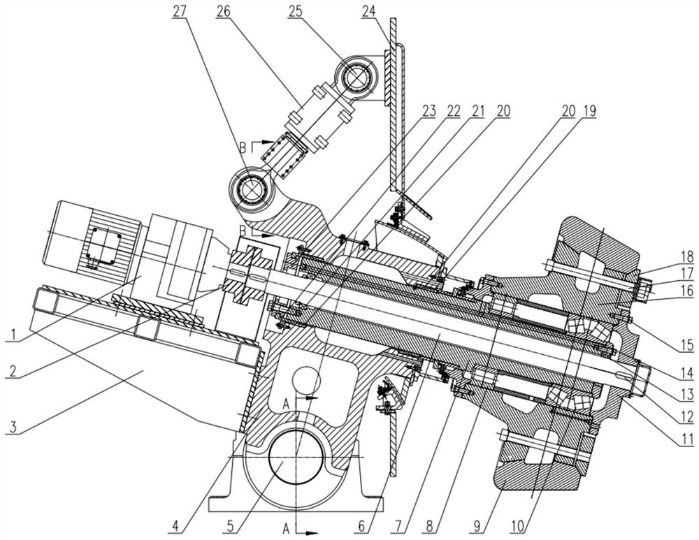
[0048] A grinding device driven by an auxiliary grinding roller includes a transmission component, an auxiliary grinding roller component, a rocker arm component, and a pressing component. The number of auxiliary grinding roller assemblies is equal to that of the main grinding rollers, and they are evenly distributed on the grinding disc and the main grinding rollers.

[0049] The main motor 48 of the vertical mill is connected to the reducer 46 through the main motor coupling 49 , the reducer 46 is connected with a grinding disc 45 , and the outer ring of the grinding disc is provided with an air duct 43 and a middle casing 40 . The main grinding roller 41 is installed in the main rocker arm 42 and fixed on the bracket 44. The connecting bridge 50 is a structural component that connects the brackets 44 for the installation of two adjacent main grinding rollers 41 into one. One end of the main roller cylinder 47 is installed on the On the bracket 44 , the other end is connecte...


PUM


Abstract

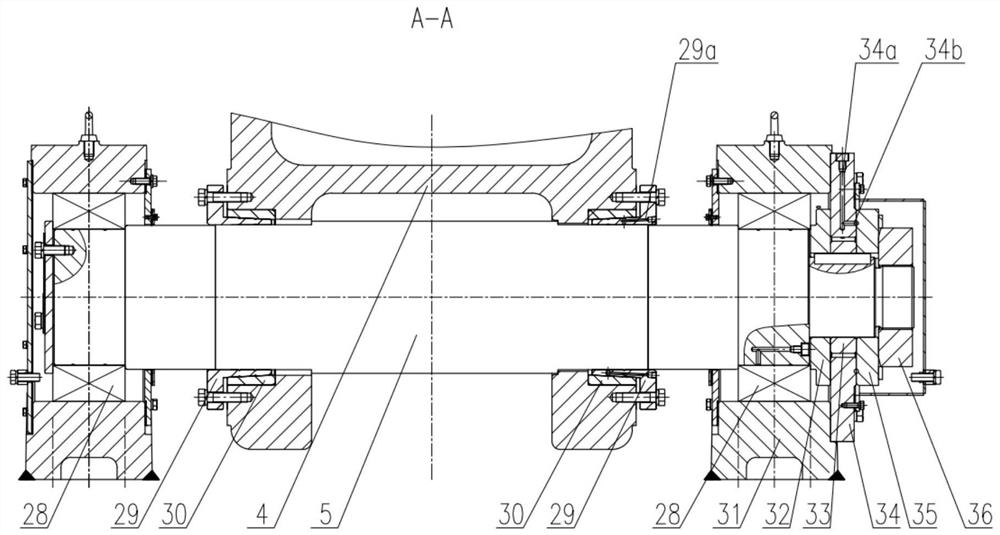
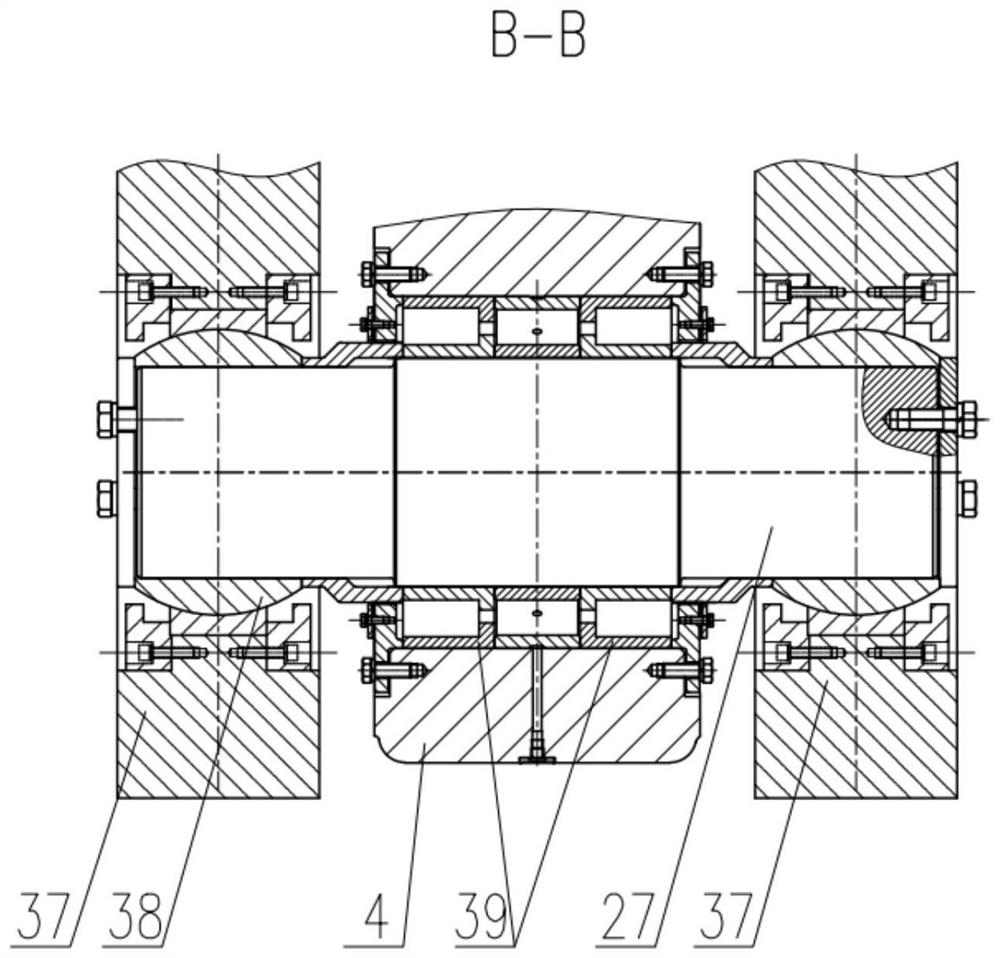
The invention belongs to the technical field of roller type vertical mill equipment, and particularly relates to a grinding device driven by an auxiliary grinding roller, the grinding device driven by the auxiliary grinding roller comprises a transmission assembly, an auxiliary grinding roller assembly, a rocker arm assembly and a pressurizing assembly, the auxiliary grinding roller assembly is fixed in a rocker arm through a hollow shaft and a grinding roller expansion sleeve; the rocker arm assembly is fixedly connected to the connecting bridge; an auxiliary roller motor in the transmission assembly is connected with a transmission shaft through a coupler, the transmission shaft is connected with a blank cap through a key, the blank cap is connected with a hub through a reamed hole bolt, and a roller sleeve is fixed to the hub through a T-shaped bolt and a pressing ring. The pressurizing assembly adopts two hydraulic oil cylinders for loading, and lower pin shafts of the oil cylinders are connected to the middle shell; an upper pin shaft of the oil cylinder is connected with an upper lug part of the rocker arm, and the auxiliary grinding roller rotates around a rocker arm shaft through the pulling force of the hydraulic oil cylinder and compacts and grinds materials on the grinding disc. The invention provides the grinding device driven by the auxiliary grinding roller, which can reduce the vibration of the grinding machine and improve the grinding efficiency.

Description

technical field [0001] The invention belongs to the technical field of vertical roller grinding equipment, and particularly relates to a grinding device driven by an auxiliary grinding roller. Background technique [0002] current technology: [0003] In the existing vertical roller mill, the main motor drives the main reducer to rotate through the coupling, thereby driving the grinding disc to rotate, and the friction force generated by the grinding material on the grinding roller drives the grinding roller to rotate, and the grinding roller rotates passively. Some vertical mills contain the same number of main grinding rolls and auxiliary grinding rolls, which are evenly staggered on the grinding disc, generally in the configuration of "2 main rolls + 2 auxiliary rolls" or "3 main rolls + 3 auxiliary rolls". Among them, the main grinding roller is responsible for grinding the material, and the material will accumulate in front of the grinding roller, which will reduce the...

Claims


Application Information

Patent Timeline
Patent Type & Authority Applications(China)
IPC IPC(8): B02C15/02
CPCB02C15/02B02C2015/008
Inventor 韩有昂赵剑波丰旺
Owner 中材(天津)粉体技术装备有限公司
Learn More