
Tunnel multichannel rapid grouting joint device and tunnel grouting system

A grouting joint and multi-channel technology, which is applied in the installation of bolts, mining equipment, earthwork drilling and mining, etc., can solve the problems of quality and safety hazards, time-consuming, lengthened bolt grouting process time, etc., to avoid safety hazards Effect

Pending Publication Date: 2022-06-24
NO 5 ENG OF CHINA RAILWAY 19 BUREAU GRP +1
View PDF0 Cites 0 Cited by
  • Summary
  • Abstract
  • Description
  • Claims
  • Application Information

AI Technical Summary

Problems solved by technology

[0003] However, in terms of the grouting construction technology of the anchor rod, a single anchor rod of the grouting machine is currently used for grouting, mainly because the grouting machine can only have one grouting outlet to ensure the pressure and one grouting port to connect the anchor rod. As a result, the anchor bolts can only be grouted one by one in the construction cycle, which leads to the prolongation of the anchor bolt grouting process in each cycle, and the grouting pipe needs to be disassembled and repaired after the grouting of each anchor bolt is completed. To connect the next bolt, it takes a long time to take over the pipe back and forth and the grouting process is cumbersome, which eventually leads to a long construction process of the entire bolt; what's more, some construction workers deliberately reduce the The number of grouting bolts cut corners and materials, resulting in hidden dangers to quality and safety

Method used


Image

  • Tunnel multichannel rapid grouting joint device and tunnel grouting system
  • Tunnel multichannel rapid grouting joint device and tunnel grouting system
  • Tunnel multichannel rapid grouting joint device and tunnel grouting system

Examples


Embodiment Construction

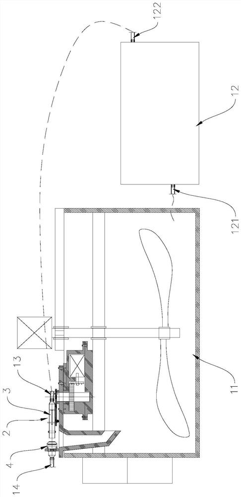
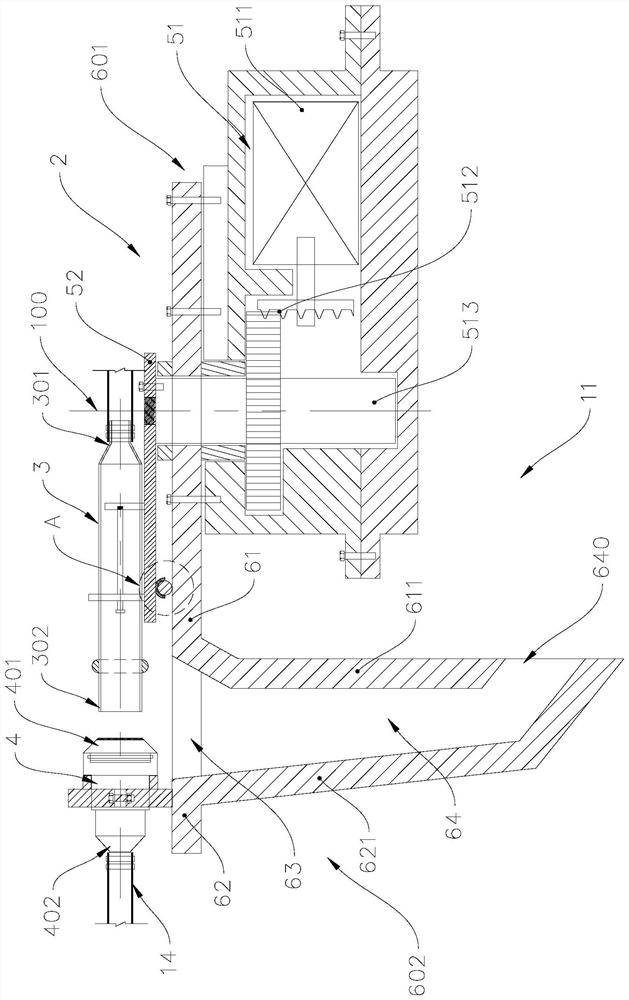
[0036] see figure 1, The tunnel grouting system is used for radial grouting of multiple hollow bolts that have been laid. The tunnel grouting system includes a slurry mixing drum 11, a grouting machine 12, the tunnel multi-channel quick grouting joint device 2 of the present invention, and a plurality of hollow bolts (not shown in the figure) that need to be grouted. shown), the tunnel multi-channel quick grouting joint device 2 includes a second grouting hose 13, a push pipe 3, a joint 4 and a first grouting hose 14, and the outlet of the slurry mixing drum 11 is connected to the outlet of the grouting machine 12. The grouting port 121 communicates with the grouting machine 12 , and the grouting machine 12 communicates with the first extension end of the second grouting hose 13 , and the second extension end of the second grouting hose 13 communicates with the input end of the push pipe 3 31 is connected, the output end 32 of the push pipe 3 is selectively connected with one...


PUM


Abstract

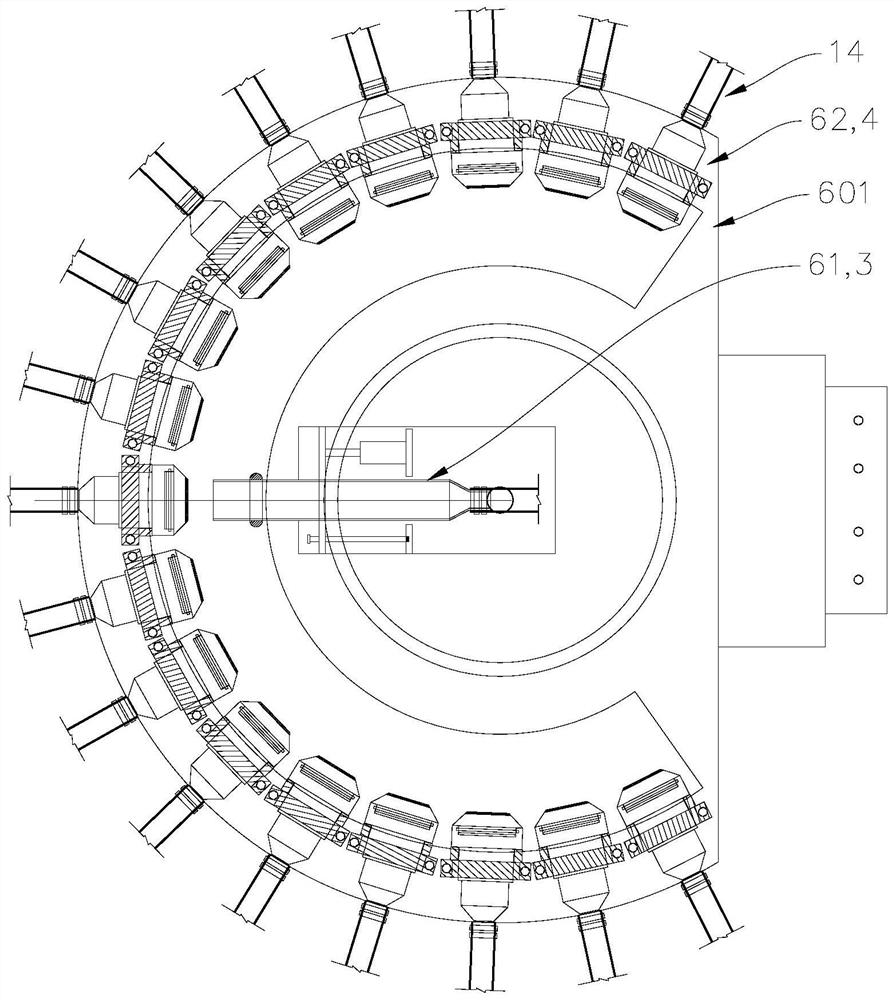
The invention provides a tunnel multi-channel rapid grouting joint device and a tunnel grouting system. The tunnel multi-channel rapid grouting joint device comprises a first grouting hose, a joint, a pushing pipe, a base, a linear driving unit, a rotary driving unit and a second grouting hose. The first grouting hose is in butt joint with the hollow anchor rod; the second grouting hose is communicated with a grout outlet of the grouting machine, and the second grouting hose is communicated with the input end of the pushing pipe; the base can rotate, the pushing pipe is arranged on the base, and the pushing pipe can move between a connection position and a separation position in the radial direction under the driving of the linear driving unit; the multiple connectors are arranged on the periphery of the first axis in the circumferential direction of the first axis. A convex edge is arranged on the periphery of the pipe wall of the output end; the quick connection end of the connector is provided with a rotatable and swingable sealing piece, and when the pushing pipe is located at the connection position, the sealing piece abuts against the pushing pipe. The tunnel grouting system comprises the tunnel multi-channel rapid grouting joint device. According to the invention, multi-channel rapid grouting is realized, and the working efficiency is improved.

Description

technical field [0001] The invention relates to the technical field of tunnel construction equipment, in particular to a tunnel multi-channel quick grouting joint device and a tunnel grouting system used in the initial support of tunnel construction. Background technique [0002] In the construction of tunnel engineering, bolts play an important role as an important system of initial support. When the radial system bolts are evenly arranged along the tunnel circumferential direction, the number of bolts in each cycle is relatively large. No matter whether the bolts are set by manual hand pneumatic drilling, or the bolts are set by rock drilling rigs or bolt drilling machines, the drilling And the installation of hollow bolts has a significant speed improvement. [0003] However, in terms of the grouting construction technology of the bolt, the grouting machine is currently used for grouting a single bolt, mainly because the grouting machine can only have a grouting outlet t...

Claims


Application Information

Patent Timeline
IPC IPC(8): E21D20/02
CPCE21D20/02E21D20/028
Inventor 刘国强杨军畅立峰高翔杨静伟王俊涛刘超刘里静李占华
Owner NO 5 ENG OF CHINA RAILWAY 19 BUREAU GRP
Learn More