
A grouting reinforcement method for coal mine fault fracture zone based on tracer technology

A tracer technology and grouting reinforcement technology, applied in mining equipment, earthwork drilling, mining equipment, etc., can solve the problems of heavy workload, lack of pertinence, water waste, etc., and achieve simple construction, high excavation efficiency, and energy saving The effect of material cost

Active Publication Date: 2020-12-18
SHANDONG UNIV OF SCI & TECH
View PDF8 Cites 0 Cited by
  • Summary
  • Abstract
  • Description
  • Claims
  • Application Information

AI Technical Summary

Problems solved by technology

In addition, there is a method of grouting reinforcement with densely distributed holes in the whole range. This method of hole distribution is heavy workload, and it is not targeted, and the effect of grouting is not obvious; or the change of water injection pressure can be used to determine the development of cracks before grouting. In this case, it not only caused a lot of water waste, but also can only judge the degree of development of fissures in the fault fracture zone by experience, and the error is very large.

Method used


Image

  • A grouting reinforcement method for coal mine fault fracture zone based on tracer technology
  • A grouting reinforcement method for coal mine fault fracture zone based on tracer technology
  • A grouting reinforcement method for coal mine fault fracture zone based on tracer technology

Examples


Embodiment 1

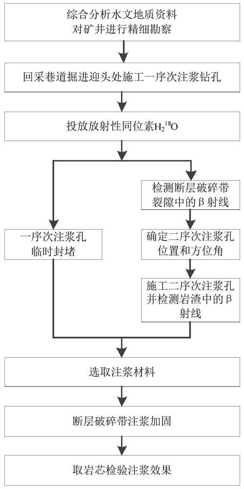
[0032] A method of grouting reinforcement for coal mine fault fracture zones based on tracer technology, such as figure 1 As shown, the specific steps include:

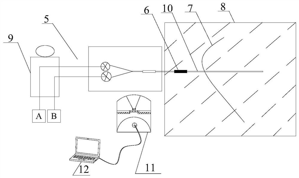
[0033] Step A. When the recovery roadway is 8-12m away from the fault, stop the excavation and drill a sequential grouting hole 1 on the side of the fault in the excavation work, and inject isotope tracers through the sequential grouting hole 1 . When the mining roadway 4 is excavated to 10m away from the fault, the excavation is suspended, and the first-order grouting drilling 1 is arranged in the shape of a square, and the isotope tracer is selected as H 2 18 O. isotope tracer in H 2 After being evenly stirred in the O, it is pumped into the first-order grouting borehole 1, and the first-order grouting borehole 1 is arranged along the edge of the excavation working face section.

[0034] The distance from the excavation working face of mining roadway 4 to the fault is judged according to the hydrogeological data...

Embodiment 2

[0043] In order to further explain the method of grouting reinforcement for fault fracture zones in coal mines based on tracer technology, take the 1201 working face section of a mine as an example. To avoid fault activation and water inrush when the roadway passes through the fault, increase the safety factor, carry out grouting reinforcement for the fault in front of the transport level roadway in this section, and adopt the method of grouting reinforcement for the fractured zone of the coal mine fault based on tracer technology. The specific steps include:

[0044] Step 1. Collect mine hydrogeological data, wherein the mine hydrogeological data include the location, thickness and distribution of aquifers, impact layers and aquitards, as well as the occurrence and stability of faults. When the transportation level roadway in the mining roadway-1201 section is 8-12m away from the fault, stop the excavation, and set up 4 one-sequence grouting holes on the side of the fault in t...


PUM


Abstract

The invention discloses a coal mine fault fracture zone grouting reinforcement method based on a tracer technology, and relates to the technological field of mining engineering. Firstly, first-order grouting holes are constructed in a driving face of a heading head for putting tracer agents, then a nuclear detector is used for detecting beta-rays in the driving face of the heading head, and the construction positions and azimuth angles of second-order grouting holes are determined according to detecting results; the radioactivity of rock slag discharged in the grouting and drilling construction process is detected and recorded, and appropriate grouting materials are selected according to detecting results; and finally grouting reinforcement is carried out on key areas. The method solves the technical problem about how to effectively grout in the roadway excavation process, can also determine the occurrence of faults and the development degree of fracture zone fractures, and has the advantages of simple construction, the wide application range and the like.

Description

technical field [0001] The invention relates to the technical field of mining engineering, in particular to a high-efficiency grouting reinforcement method for fault fracture zones in coal mines based on tracer technology. Background technique [0002] In areas with complex coal mining conditions, especially where faults are distributed, the mining roadway in the working face will inevitably pass through the fault during the excavation process. Due to the fragility of the fault itself, the roadway is prone to fault activation and water inrush when passing through the fault. Therefore, the roadway is close to the fault. , it is necessary to stop the excavation and carry out grouting reinforcement to the fault zone. [0003] Due to the uneven distribution of the fault stress zone, derivative cracks will be generated near the fault plane, forming a certain range of broken zones. The conventional floor grouting method can only generally seal and strengthen the local cracks in t...

Claims


Application Information

Patent Timeline
Patent Type & Authority Patents(China)
IPC IPC(8): E21D11/10E21F17/18E21F17/00
CPCE21D11/10E21F17/00E21F17/18
Inventor 刘伟韬刘玉本宋增谋秦月云孙茜徐百超
Owner SHANDONG UNIV OF SCI & TECH
Learn More