
Herringbone gear reducer vibration reduction transmission system and application

A technology of gear reducer and transmission system, applied in the direction of gear transmission, gear vibration/noise attenuation, transmission box, etc., can solve the problems of unstable axial positioning connection between gear and shaft, complex processing technology, limited transmission power, etc. , to achieve the effect of stable and reliable assembly and disassembly, large contact area and strong structural connection strength

Pending Publication Date: 2022-06-24
NORTHWESTERN POLYTECHNICAL UNIV
View PDF3 Cites 0 Cited by
  • Summary
  • Abstract
  • Description
  • Claims
  • Application Information

AI Technical Summary

Problems solved by technology

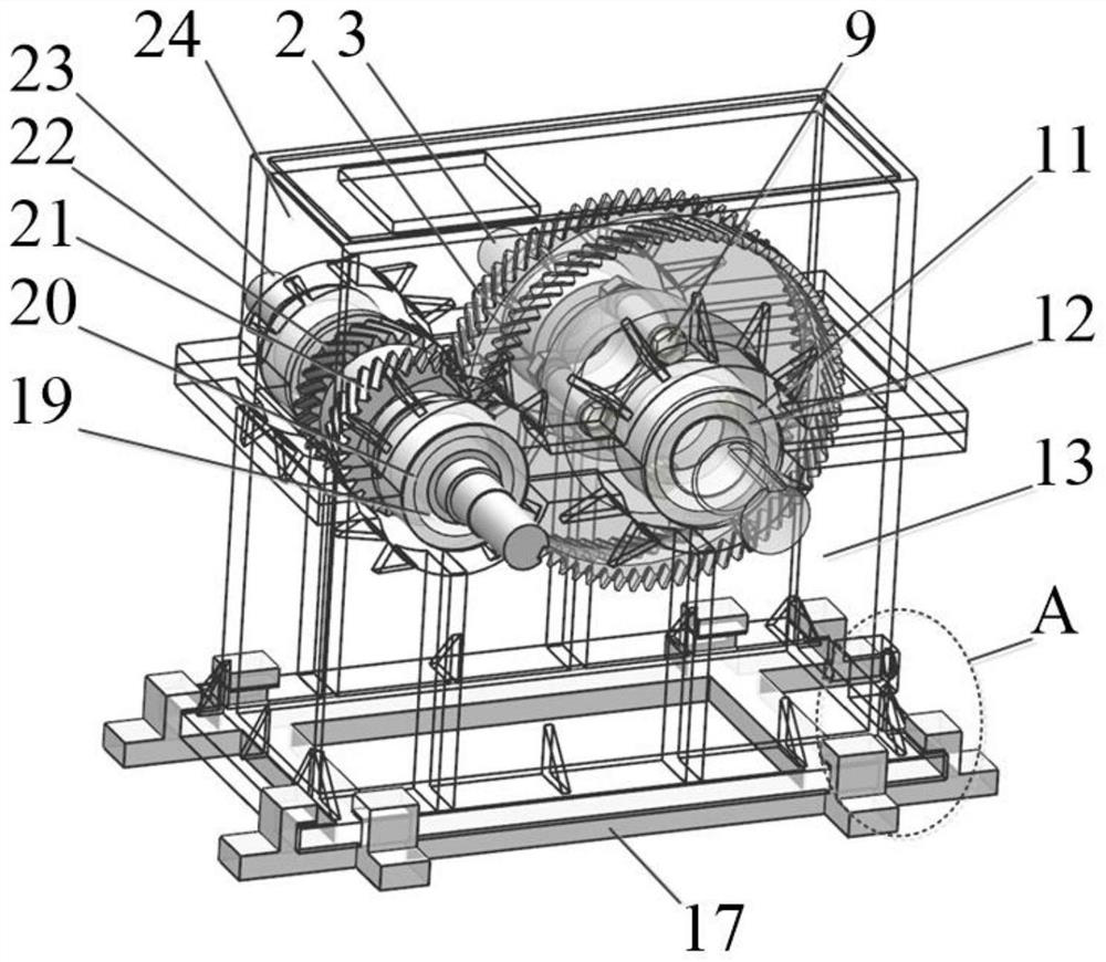
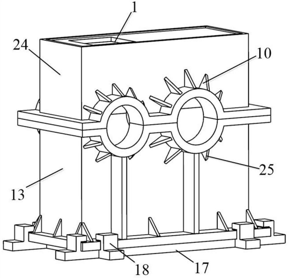
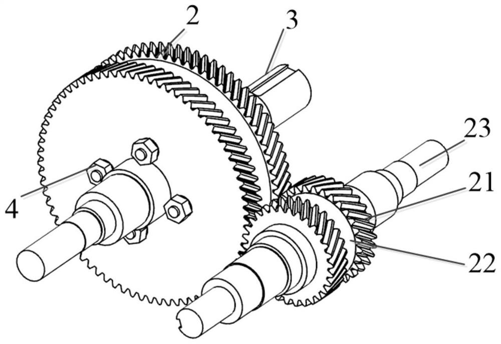
[0005] In order to avoid the deficiencies of the existing technology, and to overcome the complex process of connecting gears and shafts through keys or splines in the current navigation field, the transmission power is limited, and the axial positioning and connection of gears and shafts is unstable, and the structural vibration is insufficient. The invention proposes a vibration-damping transmission system of a herringbone gear reducer. The herringbone gear and the transmission shaft are joined by the pin with the elastic sleeve and the conical surface of the nut. The power is from the gear shaft through the active herringbone gear and the passive herringbone gear. Mesh with each other, and then the passive herringbone gear transmits to the output shaft through the conical surface, the transmission power is large and the stability is good, and the elastic sleeve between the column pin and the output shaft can ease the impact and absorb the vibration; the bottom of the box and the base Relying on the constrained damping structure for vibration absorption, the internal excitation from the gear transmission and the external excitation of the box can be well compensated to prevent transmission to the foundation, thereby achieving the purpose of vibration reduction and noise reduction

Method used


Image

  • Herringbone gear reducer vibration reduction transmission system and application
  • Herringbone gear reducer vibration reduction transmission system and application
  • Herringbone gear reducer vibration reduction transmission system and application

Examples


Embodiment Construction

[0038] The embodiments described below with reference to the accompanying drawings are exemplary, and are intended to explain the present invention and should not be construed as limiting the present invention.

[0039] In the description of the present invention, it should be understood that the terms "center", "longitudinal", "lateral", "length", "width", "thickness", "upper", "lower", "front", " rear, left, right, vertical, horizontal, top, bottom, inside, outside, clockwise, counterclockwise, etc., or The positional relationship is based on the orientation or positional relationship shown in the accompanying drawings, which is only for the convenience of describing the present invention and simplifying the description, rather than indicating or implying that the referred device or element must have a specific orientation, be constructed and operated in a specific orientation, Therefore, it should not be construed as a limitation of the present invention.

[0040] refer to...


PUM


Abstract

The invention discloses a herringbone gear speed reducer vibration reduction transmission system and application, and belongs to the technical field of speed reducers. Comprising a box body and a gear pair mounted in the box body, the gear pair comprises a driving gear and a driven gear; the driving gear is coaxially and fixedly mounted on the input shaft; the driven gear is coaxially and fixedly installed on the output shaft through a plurality of pin assemblies arranged in the circumferential direction. The pin assembly comprises an elastic sleeve, a pin and a nut, and the elastic sleeve is coaxially arranged on the peripheral face of the pin in a sleeving mode. The pin sleeved with the elastic sleeve is sequentially inserted into a shaft shoulder through hole of the output shaft and an outer end face through hole of the driven gear, and the output shaft and the driven gear are pressed and fixed through matching installation of a nut and a thread at the bottom end of the pin. Conical surface matching is achieved between the driven herringbone gear and the output shaft through the action of the pin, the nut and the gasket, fixing is achieved through pressure generated by tightening torque, the contact area is large, and operation is stable and reliable.

Description

technical field [0001] The invention belongs to the technical field of reducers, in particular to a vibration reduction transmission system of a herringbone gear reducer and its application. Background technique [0002] Due to its special conditions of use, such as large loads and harsh working conditions, the large-scale marine gear transmission system has a comprehensive technical index far higher than that of other fields of gearbox systems, and is a complex high-speed gear transmission system. Compared with helical gears, herringbone gears are difficult to control in base pitch error control, modification design and noise control, but they have outstanding advantages such as high stability, low noise, large bearing capacity, and low elimination of axial unbalanced loads. It is widely used in marine fields such as ships. [0003] Gears and shafts in the prior art gearbox are usually connected by keys, regular polygon splines, shrink fit, interference fit, etc., such as ...

Claims


Application Information

Patent Timeline
Patent Type & Authority Applications(China)
IPC IPC(8): F16H1/08F16H57/02F16H57/023F16H57/021F16H57/025F16H57/028F16H57/03F16H57/04F16D3/70
CPCF16H1/08F16H57/02F16H57/023F16H57/021F16H57/03F16H57/025F16H57/028F16H57/0018F16H57/0006F16H57/0408F16H57/0471F16D3/70
Inventor 王三民李志宾刘琳琳李飞李林林邹浩然
Owner NORTHWESTERN POLYTECHNICAL UNIV
Learn More