
Condensing unit, refrigeration equipment and refrigerator car

A technology for condensing units and refrigeration equipment, which is applied to heating/cooling equipment, refrigerators, refrigeration components, etc., can solve the problem of reducing the heat exchange efficiency of condensers and refrigeration equipment refrigeration efficiency, cold chain logistics vehicle cooling capacity cannot be guaranteed, condensation The installation space and heat exchange space are reduced to achieve the effect of increasing the flow rate, reducing the width size, and improving the heat exchange efficiency.

Pending Publication Date: 2022-06-24
SUPERCOOL SHANGHAI REFRIGERATION EQUIP
View PDF0 Cites 0 Cited by
  • Summary
  • Abstract
  • Description
  • Claims
  • Application Information

AI Technical Summary

Problems solved by technology

[0004] However, the above-mentioned technical solution is not suitable for vehicles with a small distance between the front and the compartment. When the distance between the front and the compartment is small, the installation space and heat exchange space of the condenser will be reduced accordingly, thereby reducing the condenser's capacity. Heat Exchange Efficiency and Refrigeration Efficiency of Refrigeration Equipment
Moreover, the above-mentioned technical solution is to reduce the volume of the condensing unit, and the condensing fan is omitted. The air flow rate around the condenser without the condensing fan is low, and the heat exchange between the condenser and the air is relatively passive, thereby reducing the heat transfer rate of the condenser. Thermal efficiency and refrigeration efficiency of refrigeration equipment make the cooling capacity of cold chain logistics vehicles unable to be guaranteed

Method used


Image

  • Condensing unit, refrigeration equipment and refrigerator car
  • Condensing unit, refrigeration equipment and refrigerator car
  • Condensing unit, refrigeration equipment and refrigerator car

Examples


Embodiment Construction

[0033] The present invention will be further described in detail below in conjunction with the accompanying drawings and embodiments. It should be understood that the specific embodiments described herein are only used to explain the present invention, but not to limit the present invention. In addition, it should be noted that, for the convenience of description, the drawings only show some but not all structures related to the present invention.

[0034] In the description of the present invention, unless otherwise expressly specified and limited, the terms "connected", "connected" and "fixed" should be understood in a broad sense, for example, it may be a fixed connection, a detachable connection, or an integrated ; It can be a mechanical connection or an electrical connection; it can be a direct connection or an indirect connection through an intermediate medium, and it can be the internal connection of two elements or the interaction relationship between the two elements....


PUM


Abstract

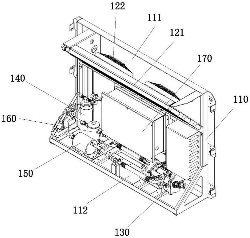
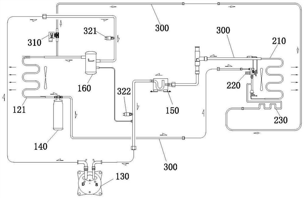
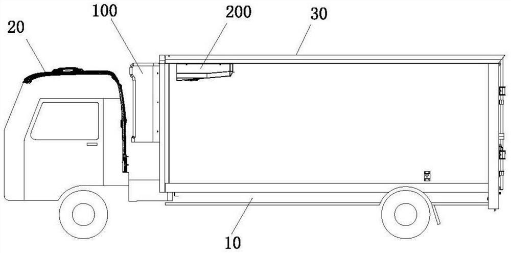
The invention belongs to the technical field of refrigeration, and discloses a condensing unit, refrigeration equipment and a refrigerator car, the condensing unit comprises a box body, a condenser and a condensing fan, a first opening is formed in the top of the box body, a second opening is formed in the bottom of the box body, the condenser is obliquely installed at the first opening in the box body, the condensing fan is installed at the first opening in the box body, and the second opening is formed in the bottom of the box body. The condenser is located on the air inlet side of the condensation fan, the air outlet side of the condensation fan is arranged towards the first opening, and the condenser still has high heat exchange efficiency under the working condition that the installation space of the condensing unit is narrow. The refrigerating unit is adopted in the refrigerating equipment and the refrigerator car, when the installation space of the condensing unit is small, the refrigerating equipment still has high refrigerating efficiency, and the cooling capacity of the refrigerator car can still be powerfully guaranteed.

Description

technical field [0001] The invention relates to the technical field of refrigeration, in particular to a condensing unit, refrigeration equipment and a refrigerated truck. Background technique [0002] With the gradual improvement of urbanization construction, large and medium-sized supermarkets are increasing day by day, and the delivery volume of food commodities has ushered in an explosive growth. In order to meet the requirements of food health and safety transportation, cold chain logistics vehicles are required for the transportation of food commodities. Chain logistics vehicles generally use top-mounted or skirted condensing unit structures, both of which will increase the overall height of the cold-chain logistics vehicle. However, most of the cargo delivery areas in large shopping malls or hotels are in underground garages, which have certain restrictions on the height of vehicles, making it impossible for commonly used cold chain logistics vehicles to drive into un...

Claims


Application Information

Patent Timeline
IPC IPC(8): F25B39/04F25B31/00F25B43/00F25B1/04B60H1/32B60P3/20
CPCF25B39/04F25B31/00F25B43/006F25B1/04B60H1/3227B60H1/3232B60H1/3223B60P3/20F25B2500/01
Inventor 翟伟伟倪正才谢皓李丹阳
Owner SUPERCOOL SHANGHAI REFRIGERATION EQUIP
Learn More