Lithography machine matching method

A matching method and lithography machine technology, applied in the field of lithography machines, can solve problems such as performance differences of lithography machines, and achieve the effect of enhancing reliability

Pending Publication Date: 2022-06-24
DONGFANG JINGYUAN ELECTRON LTD
View PDF0 Cites 0 Cited by
  • Summary
  • Abstract
  • Description
  • Claims
  • Application Information

AI Technical Summary

Problems solved by technology

[0004] In order to solve the problem of performance differences between multiple lithography machines used in the same production line, the present invention provides a matching method for lithography machines

Method used


Image

  • Lithography machine matching method
  • Lithography machine matching method
  • Lithography machine matching method

Examples


Embodiment Construction

[0059] In order to make the objectives, technical solutions and advantages of the present invention clearer, the present invention will be further described in detail below with reference to the accompanying drawings and implementation examples. It should be understood that the specific embodiments described herein are only used to explain the present invention, but not to limit the present invention.

[0060] As used herein, the terms "vertical", "horizontal", "left", "right", "top", "bottom", "top left", "top right", "bottom left", "bottom right" and the like The expressions are for illustrative purposes only.

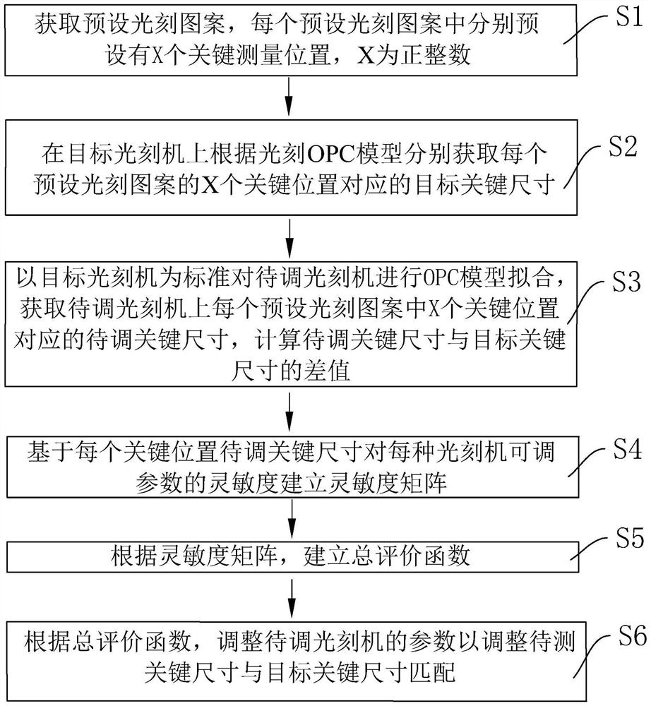
[0061] see figure 1 , the first embodiment of the present invention provides a lithography machine matching method for matching multiple lithography machines on the same production line, including the following steps:

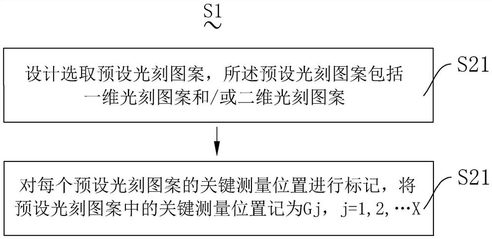
[0062] Step S1: obtaining preset lithography patterns, X key positions are preset in each preset lithography pattern, and X is a positive integer; ...


PUM


Abstract

The invention relates to the technical field of photoetching machines, in particular to a photoetching machine matching method, which comprises the following steps: acquiring preset photoetching patterns, respectively presetting X key positions in each preset photoetching pattern, and X being a positive integer; respectively acquiring target key sizes corresponding to the X key positions of each preset photoetching pattern on a target photoetching machine according to the photoetching OPC model; performing OPC model fitting on the to-be-adjusted photoetching machine by taking the target photoetching machine as a standard, obtaining to-be-adjusted key sizes corresponding to X key positions in each preset photoetching pattern on the to-be-adjusted photoetching machine, and calculating a difference value between the to-be-adjusted key sizes and the target key size; establishing a sensitivity matrix for the sensitivity of the adjustable parameters of each photoetching machine based on each to-be-adjusted key size; establishing a total evaluation function according to the sensitivity matrix; and adjusting parameters of the to-be-adjusted photoetching machine according to the total evaluation function so as to adjust the to-be-measured key size to be matched with the target key size.

Description

【Technical field】 [0001] The present invention relates to the technical field of lithography machines, in particular to a method for matching lithography machines. 【Background technique】 [0002] Optical process is the modeling of light with the help of mathematical formulas using optical and chemical models. The light is irradiated through the mask to form diffraction and converge on the surface of the photoresist, while the projected light stimulates a chemical reaction on the photoresist and bakes the photoresist to partially dissolve in the developing solution. By simulating the reactions that take place on the photoresist, computationally exploring ways to increase lithography resolution and process window is called lithography OPC modeling. [0003] In mass production, multiple lithography machines used in the same production line may come from different lithography machine suppliers. The function and performance of the lithography process of the chip may be differen...

Claims


Application Information

Patent Timeline
Patent Type & Authority Applications(China)
IPC IPC(8): G03F7/20
CPCG03F7/70458G03F7/70441G03F7/705G03F7/70625
Inventor 王成瑾张生睿
Owner DONGFANG JINGYUAN ELECTRON LTD
Why Eureka
Try Eureka