Puncher and operation method thereof
A puncher and knife holder technology, applied in the field of puncher, can solve problems such as complex structure, unevenness, deformation of heart tissue, etc.
- Summary
- Abstract
- Description
- Claims
- Application Information
AI Technical Summary
Problems solved by technology
Method used
Image
Examples
Embodiment 1
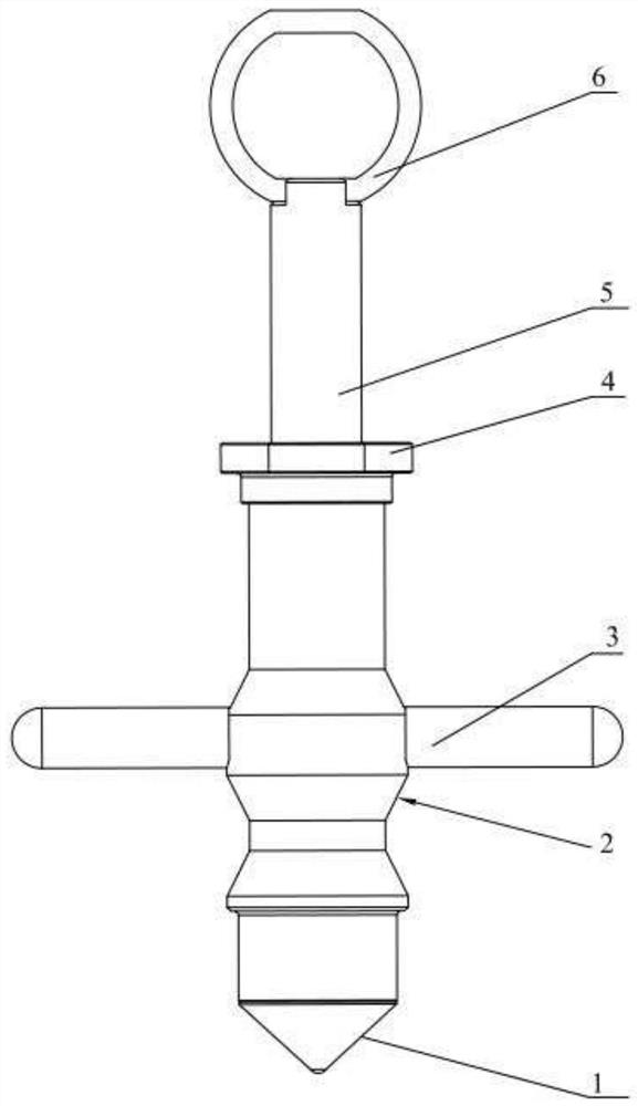
[0062] Please refer to figure 1 , The punch provided by the first embodiment is mainly used to punch holes in the ventricular wall, and the punch includes a knife holder 2, a driving member, a cutting component and a pressing component.
[0063] Wherein, the tool holder 2 has a through portion penetrating through the tool holder 2 in the axial direction.
[0064] The driving member has a through portion which is at least partially movably arranged on the tool holder 2 .
[0065] The proximal end of the cutting assembly is connected with the driving member, so as to drive the cutting assembly to move axially relative to the tool holder 2 through the driving member;
[0066] The proximal end of the pressing component is movably arranged on the cutting component, and the distal end of the pressing component is arranged on the outside of the knife holder 2, so as to drive the pressing component relative to the knife holder 2 when the driving member moves. The tool holder 2 moves...
Embodiment 2
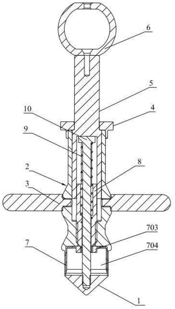
[0111] Please refer to figure 2 , the hole punch described in the second embodiment of the present invention is basically the same as the first embodiment, and the same parts are not described, and only the differences are described below.
[0112] Please continue to refer to figure 2In the hole punch provided in the second embodiment, the proximal end of the second shaft 10 still passes through the fifth inner cavity 804 of the first shaft 8 and into the third inner cavity 504 of the tool handle 5, but The proximal end of the second shaft 10 penetrating into the third inner cavity 504 is fixedly connected with the tool handle 5 to form an integral structure. When the proximal end of the second shaft 10 is fixedly connected with the handle 5, there is no need to set the spring 9 on the outside of the second shaft 10, and the user can manually push and pull the pull ring 6, so that the handle 5 is The second shaft 10 can be driven to move synchronously, so as to realize the...
PUM
 Abstract
Description
Claims
Application Information
 - R&D
- Intellectual Property
- Life Sciences
- Materials
- Tech Scout
- Unparalleled Data Quality
- Higher Quality Content
- 60% Fewer Hallucinations
Browse by: Latest US Patents, China's latest patents, Technical Efficacy Thesaurus, Application Domain, Technology Topic, Popular Technical Reports.
© 2025 PatSnap. All rights reserved.Legal|Privacy policy|Modern Slavery Act Transparency Statement|Sitemap|About US| Contact US: help@patsnap.com


