Displacement sensing device of robot and feedback control method

A sensing device and robot technology, applied in the field of robotics, can solve the problems such as the robot cannot reach the preset position, the position control of the body is not accurate, and the position accuracy of the body is affected, and the connection is free to swing, avoid errors, and have a simple and compact structure. Effect

Pending Publication Date: 2022-06-28
GUANGZHOU POWER SUPPLY BUREAU GUANGDONG POWER GRID CO LTD
View PDF1 Cites 0 Cited by
  • Summary
  • Abstract
  • Description
  • Claims
  • Application Information

AI Technical Summary

Problems solved by technology

However, in actual work, the surface on which the fuselage walks is generally uneven, so that the fuselage will bump when it walks, and the relative position will shift to a certain extent, which will affect the accuracy of the relative displacement detection of the fuselage position, resulting in the position of the fuselage The control is not precise, which may cause the robot to fail to reach the preset position and fail to complete the work in severe cases

Method used


Image

  • Displacement sensing device of robot and feedback control method
  • Displacement sensing device of robot and feedback control method
  • Displacement sensing device of robot and feedback control method

Examples


Embodiment 1

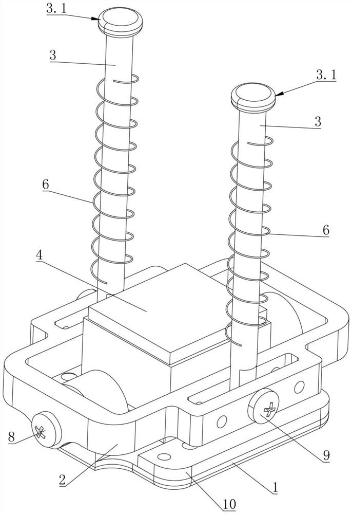
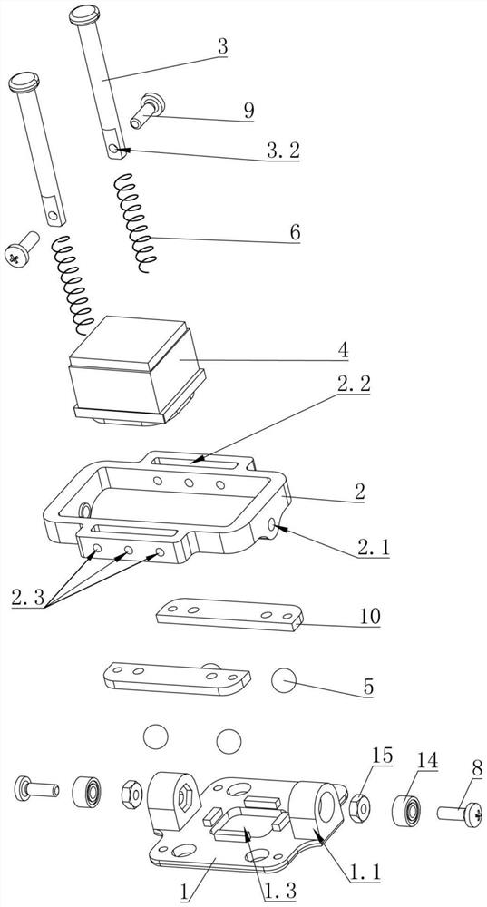
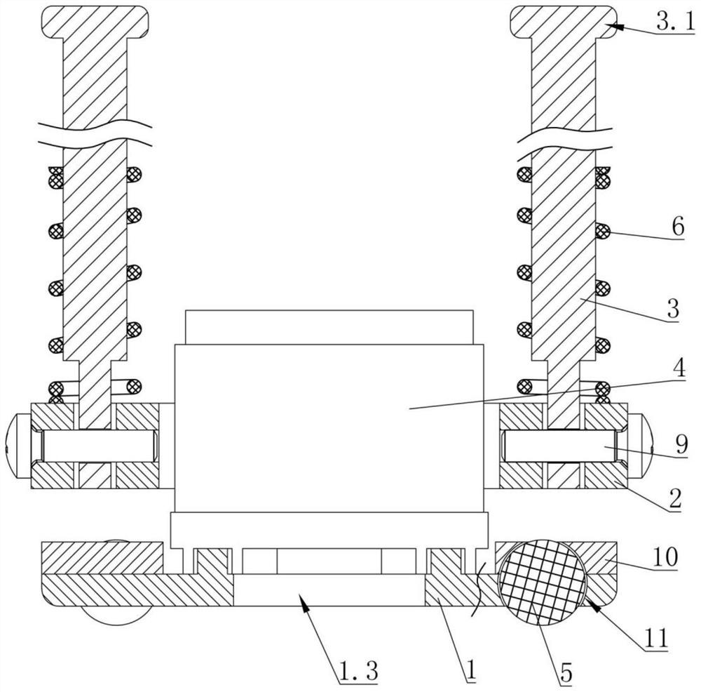
[0033] like Figure 1 to Figure 4As shown, the present embodiment is a displacement sensing device for a robot, including a bottom plate 1, a movable plate 2 and a connecting rod 3, the bottom plate 1 is connected with an optical navigation sensor module 4, and the bottom of the bottom plate 1 is rollingly connected with balls 5; The plate 2 is rotatably connected with the bottom plate 1, one end of the connecting rod 3 is rotatably connected with the movable plate 2, and the other end of the connecting rod 3 is floatingly connected to the body of the robot; The extension directions of the connecting rods 3 are perpendicular to each other.

[0034] The fuselage is provided with a sliding hole, the top of the connecting rod 3 passes through the sliding hole and a limit block 3.1 is protruded, and the limit block 3.1 cooperates with the stopper of the fuselage; a first elastic member is arranged between the fuselage and the movable plate 2 6. The first elastic member 6 always h...

Embodiment 2

[0052] like Figure 5 As shown, compared with the first embodiment, the bottom of the fuselage is provided with a guide rail plate 7, the guide rail plate 7 is provided with a guide sleeve 7.1 corresponding to the sliding hole, and the top end of the connecting rod 3 passes through the guide sleeve 7.1, The limit block 3.1 is matched with the guide sleeve 7.1 to stop. The guide rail plate 7 is firmly connected to the bottom of the fuselage by bolts, and the guide sleeve 7.1 is in clearance fit with the connecting rod 3; the guide sleeve 7.1 can better guide the connecting rod 3, so that the connecting rod 3 can only follow the guide sleeve 7.1. The axial floating, that is, in the vertical direction, can avoid the possibility of tilt, make the movement more stable, and effectively improve the detection accuracy.

Embodiment 3

[0054] like Image 6 and Figure 7 As shown, compared with the first embodiment, the structure of the cover plate 10 in the first embodiment is omitted, the bottom plate 1 is provided with a mounting hole 1.2 for accommodating the ball 5, and the bottom end of the mounting hole 1.2 is provided with a limit ring 12. A second elastic member 13 is arranged in the mounting hole 1.2. The second elastic member 13 always has a tendency to drive the ball 5 against the limiting ring 12 and expose the part of the ball 5 to the outside of the bottom of the bottom plate 1.

[0055] The mounting hole 1.2 can be a blind hole opened in the vertical direction, the limit ring 12 is screwed to the bottom end of the mounting hole 1.2, and the second elastic member 13 is abutted between the bottom of the mounting hole 1.2 and the ball 5, limiting the position The contact surface of the hole 12 and the ball 5 is a matching arc surface, which can better restrain the ball 5, the connection is more ...


PUM


Abstract

The invention discloses a displacement sensing device of a robot and a feedback control method, the displacement sensing device comprises a bottom plate, a movable plate and a connecting rod, the bottom plate is connected with an optical navigation sensing module, and the bottom of the bottom plate is in rolling connection with a ball; the movable plate is rotationally connected with the bottom plate, one end of the connecting rod is rotationally connected with the movable plate, and the other end of the connecting rod is connected to a robot body in a floating mode. The rotating axis of the bottom plate, the rotating axis of the connecting rod and the extending direction of the connecting rod are arranged in a pairwise perpendicular mode. The device has the advantages of being simple in structure, reliable in connection and capable of swinging freely, the relative displacement deviation is effectively reduced, the detection precision is improved, and precise control over the position of the machine body is achieved.

Description

technical field [0001] The invention relates to the technical field of robots, in particular to a displacement sensing device and a feedback control method of a robot. Background technique [0002] A robot is an intelligent machine that can work semi-autonomously or fully autonomously. Robots have basic characteristics such as perception, decision-making, and execution. They can assist or even replace humans in completing dangerous, heavy and complex work, improve work efficiency and quality, serve human life, and expand or extend the scope of human activities and capabilities. Therefore, there is an urgent need to solve the above problems. [0003] At present, mobile robots can usually perform moving operations according to programming and automatic control, so as to reach a preset position, and during the movement of the fuselage, automatic line inspection, navigation, obstacle avoidance, Follow, detect, etc. For example, the Chinese Patent Application No. CN20211074285...

Claims


Application Information

Patent Timeline
Patent Type & Authority Applications(China)
IPC IPC(8): B25J9/16B25J5/00
CPCB25J9/1664B25J9/1694B25J5/007
Inventor 蔡蒂程思敏曾文斐丛培杰李晨涛黄家棋张铁薛泽浩
Owner GUANGZHOU POWER SUPPLY BUREAU GUANGDONG POWER GRID CO LTD
Why Eureka
Try Eureka