
Corrugated wall building and installation method thereof

A corrugated and wall technology, applied in the direction of architecture, building components, building structures, etc., can solve the problems of large components, large welding volume, large height and width, etc., to increase the overall rigidity, fast installation speed, and increased rigidity Effect

Pending Publication Date: 2022-06-28
刘旭
View PDF0 Cites 0 Cited by
  • Summary
  • Abstract
  • Description
  • Claims
  • Application Information

AI Technical Summary

Problems solved by technology

It is found that the biggest problem is the problem caused by the weight of the component and the large height and width: 1. Difficulty in installation
2. The transportation is super high or super wide, and the transportation is extremely difficult, and it is even more difficult to transport it in containers for export
3. The amount of welding is relatively large in the manufacture of components, which cannot completely realize the assembly line production
In addition, there are many doors and windows in the building, accounting for a relatively large proportion. How to design the structure of the doors and windows, how to standardize the components for making doors and windows, and how to make the designed door and window structure can be produced on the production line are also difficult problems.

Method used


Image

  • Corrugated wall building and installation method thereof
  • Corrugated wall building and installation method thereof
  • Corrugated wall building and installation method thereof

Examples


Embodiment 1

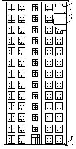
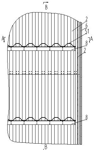
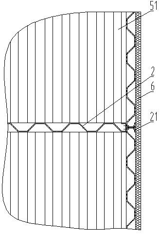
[0057] like figure 1 figure 2 image 3 As shown, the corrugated wall construction of the present invention comprises: a corrugated wall 1, the corrugated wall 1 includes a corrugated wallboard 2, and the corrugated wallboard is a trapezoidal corrugated wallboard, a groove-shaped corrugated wallboard or Concave-convex corrugated wall panels. The upper and lower adjacent corrugated wall panels 2 are overlapped and then connected by screw parts or through the transition piece 3 to form the heightened corrugated wall panels. The corrugated wall panels have no beams, and the corrugated wall panels without beams It can be produced directly through the assembly line, and the production and installation are very convenient, and the beam material and production cost can be saved. The left and right adjacent corrugated wall panels are connected by screws or welded to form the widened corrugated wall panels. In this connection, the width of the corrugated wall panels can be reduced, ...

Embodiment 2

[0059] The corrugated wall construction described in embodiment 1, such as Figure 16 , Figure 17 , Figure 18 , Figure 19 As shown, the upper part of the door and / or window has a plate body beam 7, and the plate body beam 7 is connected with the adjacent corrugated wallboard screw to form the door or window together, and the plate The body beam is a corrugated plate body beam 71 or a grooved plate body beam 72 . The slab beam of the present invention has the functions of the beam and the wall on the upper part of the traditional doorway and window.

Embodiment 3

[0061] The corrugated wall construction described in embodiment 1 or 2, such as figure 2 , Figure 4 , Figure 15 As shown, the side of the corrugated wall has a reinforcing beam 8, the floor slab 5 is installed on the reinforcing beam 8 or on the corrugated wall 1, and the corrugated wall panel 2 is a plane corrugated wall panel Or arc corrugated wallboard or right angle corrugated wallboard 22.


PUM


Abstract

The invention discloses a corrugated wall building and a mounting method, and aims to solve the problems that the existing steel structure building is a frame structure system, needs to independently manufacture a wall and is only suitable for large-space house body construction, and no good scheme is provided for a steel structure assembly type house. The corrugated wall body building comprises a corrugated wall body, the corrugated wall body comprises corrugated wall plates, the upper and lower adjacent corrugated wall plates are connected to form a heightened corrugated wall plate after being lapped, the left and right adjacent corrugated wall plates are connected to form a widened corrugated wall plate, and the corrugated wall plates at 90-degree horizontal adjacent positions are connected through corrugated wall plate columns or connecting columns. The corrugated wallboards are assembled and connected to form an L-shaped or T-shaped or cross-shaped node wall, the corrugated wallboards jointly form a corrugated wall body, the corrugated wall body is connected with a floor slab and a stair, and the top of the corrugated wall body is connected with a roof; bottom beams are installed at the bottoms of the corrugated wall bodies and connected with a foundation, the corrugated wall bodies are provided with doors and windows, and heat preservation and insulation layers are installed on the side faces of the peripheral corrugated wall bodies. The steel structure corrugated wall building is used for steel structure corrugated wall buildings.

Description

technical field [0001] The invention belongs to the field of construction engineering, and in particular relates to a novel steel plate shear wall building. Background technique [0002] Traditional buildings are mainly reinforced concrete buildings built with sandstone and cement as the main raw materials. A large number of high-energy building materials such as sandstone and cement are used in construction, which has caused a great burden on the ecological environment. The main change of the existing prefabricated buildings is from on-site pouring to factory prefabrication, which reduces the labor and improves the efficiency of mold use, but there is not much change in the key aspects of energy conservation and environmental protection, cost control, and material use. , the use of materials has increased. Compared with traditional buildings, the existing prefabricated buildings are only moved from on-site construction to factory prefabrication, just changing the location,...

Claims


Application Information

Patent Timeline
Patent Type & Authority Applications(China)
IPC IPC(8): E04B1/00E04B2/00E04C2/32E04B1/61E04B1/76E04B1/38E04G21/14
CPCE04B1/00E04B2/00E04C2/32E04B1/61E04B1/76E04B1/38E04G21/14
Inventor 刘旭
Owner 刘旭
Learn More