Roller fixing structure, vehicle window lifter and vehicle

A fixed structure and window lifting technology, which is applied to door/window accessories, building structures, power control mechanisms, etc., can solve problems such as high processing difficulty, affecting structural stability, and inability to contact the connecting ends at the same time

Pending Publication Date: 2022-06-28
MAGNA AUTOMOTIVE PARTS (SUZHOU) CO LTD
View PDF0 Cites 0 Cited by
  • Summary
  • Abstract
  • Description
  • Claims
  • Application Information

AI Technical Summary

Problems solved by technology

However, the existing problem is that although the "Z"-shaped connecting part can play a certain role in facilitating installation, the two connecting ends located on both sides of the carrier need to be attached to the carrier at the same time to play a complete role, resulting in Its processing is difficult. In addition, when the assembly of the roller an

Method used


Image

  • Roller fixing structure, vehicle window lifter and vehicle
  • Roller fixing structure, vehicle window lifter and vehicle
  • Roller fixing structure, vehicle window lifter and vehicle

Examples


Embodiment 1

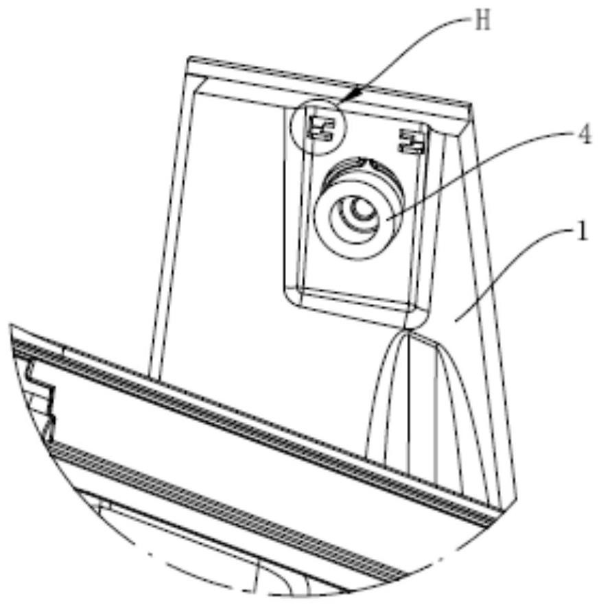
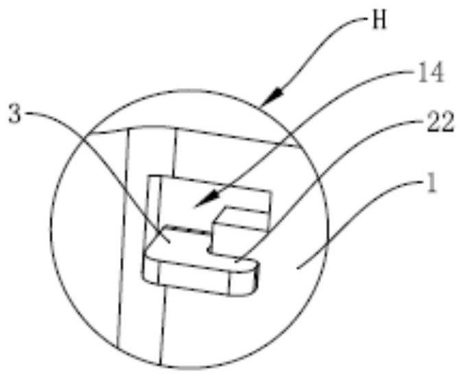
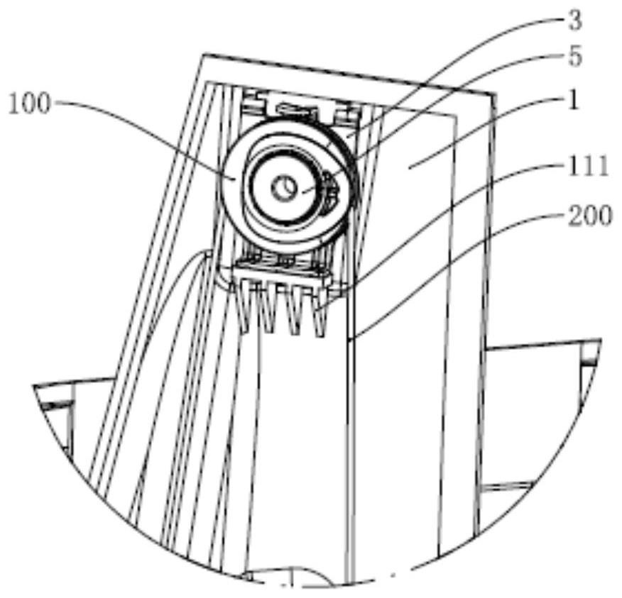
[0073] figure 1 A schematic diagram showing the structure of the roller fixing structure in the first embodiment of the present invention Figure 1 ; figure 2 Yes figure 1 Enlarged image at H in middle; image 3 A schematic diagram showing the structure of the roller fixing structure in the first embodiment of the present invention Figure II ; Figure 4 A schematic front view showing the roller fixing structure in Embodiment 1 of the present invention; Figure 5 Yes Figure 4 Cross-sectional schematic diagram of section A-A in the middle; Image 6 Yes Figure 5 Enlarged image at I. refer to Figure 1-Figure 6 , This embodiment provides a roller fixing structure, which is convenient for processing and can still be stably installed on the mounting plate when the support seat is deformed, which can be used in the technical field of window lifters.

[0074] continue to refer to Figure 1-Figure 6 , the roller fixing structure is used to install the roller 100 and the ...

Embodiment 2

[0086] Figure 7 A schematic structural diagram of the roller fixing structure in Embodiment 2 of the present invention is shown; Figure 8 A schematic front view showing the roller fixing structure in the second embodiment of the present invention; Figure 9 Yes Figure 8 Schematic cross-sectional view of the B-B section in the middle. refer to Figure 7-Figure 9 , this embodiment provides another roller fixing structure, which can also achieve the effect of the roller fixing structure in the first embodiment.

[0087] continue to refer to Figure 7-Figure 9 In this embodiment, the specific structures of the inserting block 61 and the slot 62, as well as the specific structures of the first abutting portion 11 and the third abutting portion 21 are the same as those in the first embodiment, and will not be repeated here. Different from the first embodiment, in this embodiment, the specific structure of the second abutting portion 12 and the fourth abutting portion 22 abut...

Embodiment 3

[0090] Figure 10 A schematic diagram showing the structure of the roller fixing structure in the third embodiment of the present invention Figure 1 ; Figure 11 Yes Figure 10 Enlarged image at J in middle; Figure 12 A schematic diagram showing the structure of the roller fixing structure in the third embodiment of the present invention Figure II ; Figure 13 A schematic front view showing the roller fixing structure in Embodiment 3 of the present invention; Figure 14 Yes Figure 13 Schematic cross-sectional view of the C-C section in the middle. refer to Figure 10-Figure 14 , this embodiment provides another roller fixing structure, which can also achieve the effect of the roller fixing structure in any of the above embodiments.

[0091] continue to refer to Figure 10-Figure 14 In this embodiment, the specific structures of the first abutting portion 11 and the third abutting portion 21 are the same as those in the first or second embodiment, and the specific ...


PUM


Abstract

The invention belongs to the technical field of car window lifters, and discloses a roller fixing structure which comprises a mounting plate and a supporting seat, the mounting plate is used for arranging a guide rail, and the supporting seat is used for rotationally arranging a roller. After the roller is installed, the roller applies pulling force in the first direction to the supporting seat, and the third abutting part abuts against the first abutting part in the first direction so as to generate supporting force opposite to the pulling force in direction and generate first torque. The fourth abutting part abuts against the second abutting part in the second direction and is inserted into the inserting groove through an inserting block, and the inserting block abuts against the two groove walls at the same time so as to generate a second torque used for offsetting the first torque. When the installation of the roller is not completed, the second abutting part abuts against the fourth abutting part in the second direction, and the insertion block abuts against the two groove walls at the same time, so that the supporting seat is prevented from falling off from the installation plate.

Description

technical field [0001] The invention relates to the technical field of window lifters, in particular to a roller fixing structure, a window lifter and a vehicle. Background technique [0002] The window lifter is a lifting device for the glass of automobile doors and windows. At present, the window lift generally adopts a button-type electric lifting method, that is, the window is driven to lift by a slider. In this kind of window lifter, rollers and wire rope structures are used to assist the sliding. The block slides in the preset direction, making the sliding of the slider more stable. [0003] The current window lifter is generally connected to the roller by the cantilever, and the roller is supported by the cantilever to rotate and receive force. After the wire rope and the slider are installed on the roller, the roller will exert a pulling force toward the slider along the movement direction of the slider, so that the cantilever is The force at the place is large, whi...

Claims


Application Information

Patent Timeline
IPC IPC(8): E05F15/689
CPCE05F15/689
Inventor 刘经济马玲王国亮卢迪生刘晓月
Owner MAGNA AUTOMOTIVE PARTS (SUZHOU) CO LTD
Why Eureka
Try Eureka