Coaxial reciprocating motion mechanism and appliance

A reciprocating mechanism, coaxial technology, applied in electric components, transmission devices, electromechanical devices, etc., can solve the problems that the output end cannot automatically return, cannot form a coaxial output, and the pendulum bearing is large in size, and achieves low noise. , Simple structure, small sliding friction effect

Pending Publication Date: 2022-06-28
吴吉东
View PDF3 Cites 3 Cited by
  • Summary
  • Abstract
  • Description
  • Claims
  • Application Information

AI Technical Summary

Problems solved by technology

[0007]The swash plate reciprocating mechanism has relatively large friction force, the output end cannot automatically return to its position, and a rebound mechanism needs to be added, and the working noise is loud
[0008]Eccentric wheel reciprocating mechanism, the swing rod bearing is large in size and cannot form coaxial output

Method used


Image

  • Coaxial reciprocating motion mechanism and appliance
  • Coaxial reciprocating motion mechanism and appliance
  • Coaxial reciprocating motion mechanism and appliance

Examples


Embodiment Construction

[0048] Preferred embodiments of the present invention will be described in detail below with reference to the accompanying drawings. Those skilled in the art will appreciate that these descriptions are descriptive, exemplary only, and should not be construed as limiting the scope of protection of the present invention.

[0049] It should be noted that like numerals refer to like items in the following figures, so once an item is defined in one figure, it may not be further defined and explained in subsequent figures.

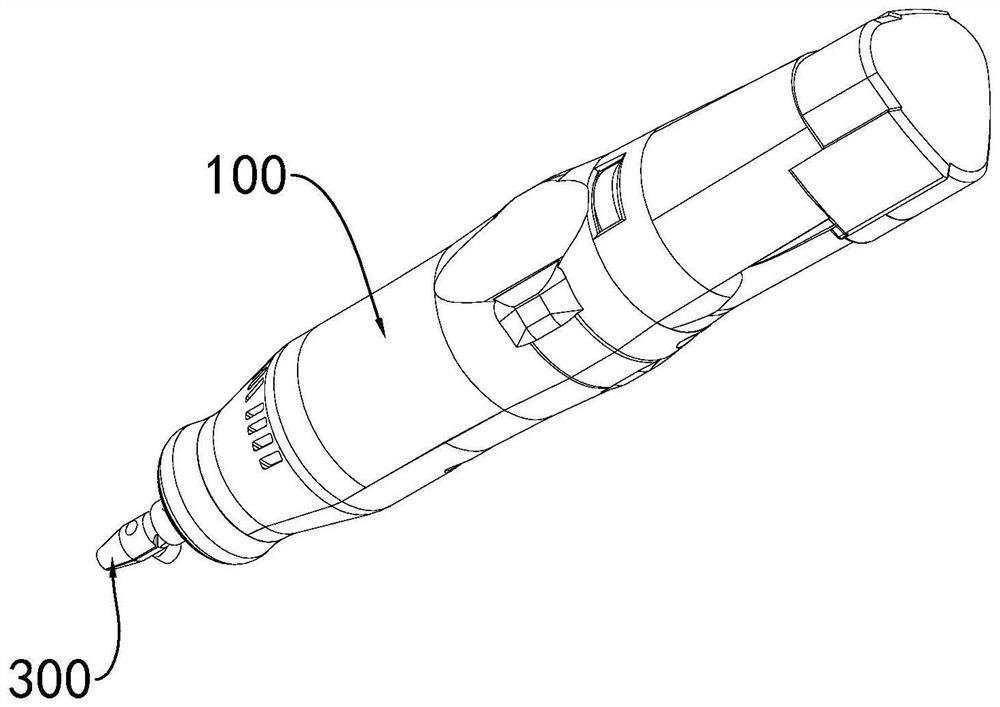
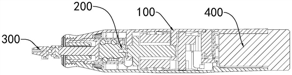
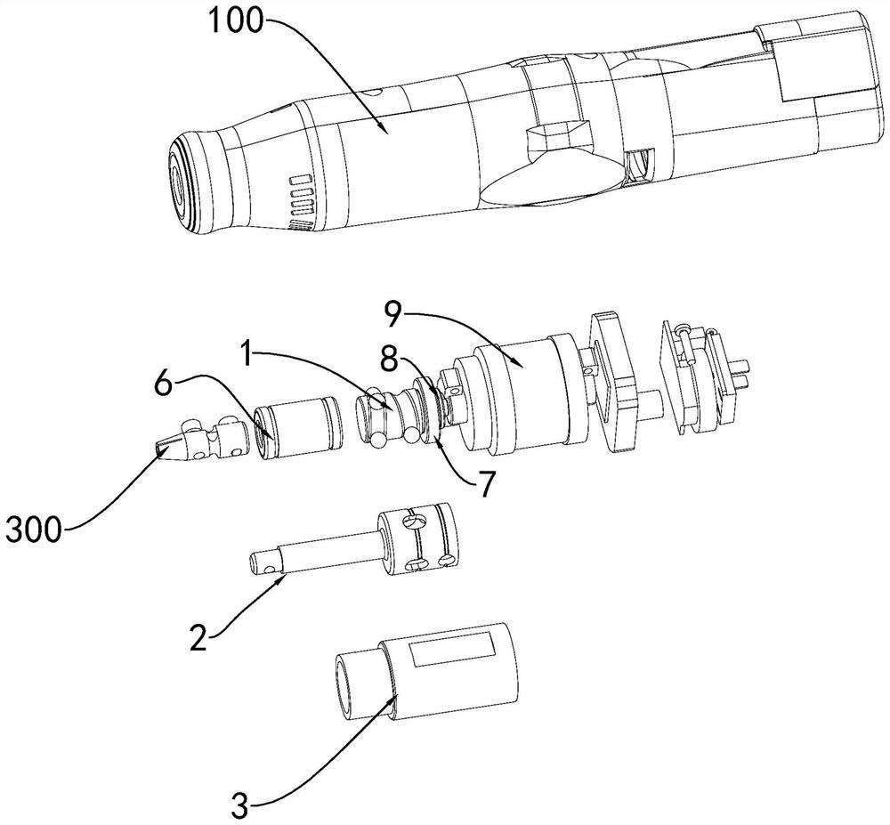
[0050] like Figure 1-3 As shown, this embodiment provides an electric file including a housing 100, a coaxial reciprocating mechanism 200 located in the housing 100, and a file connected to the front end of the coaxial reciprocating mechanism 200 and exposed at the front of the housing 100 Head 300. The movement of the coaxial reciprocating mechanism 200 makes the file head 300 move back and forth, so as to realize a straight line operation to file the surfac...


PUM


Abstract

The coaxial reciprocating motion mechanism comprises an inner rotating shaft, an output shaft and an outer sleeve, the inner rotating shaft and the output shaft are located on the same axis, and the output shaft is sleeved with the outer sleeve; the inner rotating shaft is provided with at least one annular groove surrounding the surface of the inner rotating shaft, the annular groove has a certain inclination angle relative to the cross section of the inner rotating shaft, and a positioning steel ball is arranged on the annular groove; the output shaft comprises a shaft part and a shaft sleeve at the rear end of the shaft part; the shaft sleeve is provided with a cavity for accommodating the inner rotating shaft; a positioning hole is formed in the wall of the shaft sleeve; the inner wall of the outer sleeve is provided with at least one linear groove extending in the axial direction. The positioning steel balls penetrate through the positioning holes and fall into the linear grooves; the inner rotating shaft rotates, the positioning steel ball rolls along the annular groove, is bound by the linear groove in the inner wall of the outer sleeve and slides in the linear direction, and the positioning steel ball drives the output shaft to do front-back telescopic reciprocating motion through the positioning hole; the coaxial reciprocating motion mechanism and appliance have the advantages of long service life, small size and low noise.

Description

technical field [0001] The invention relates to a reciprocating motion mechanism, in particular to a coaxial reciprocating motion mechanism and an appliance using the mechanism. Background technique [0002] Existing electric tools (reciprocating saws, electric files), fascia guns, electric toothbrushes, etc. all use reciprocating motion mechanisms. [0003] The fascia gun of CN112263459A includes a reciprocating motion mechanism, which adopts an eccentric wheel to drive a sliding block to reciprocate through a sliding rod. [0004] The electric toothbrush of CN200957117Y includes a rotatable transmission shaft arranged in the brush head, an eccentric shaft is installed on the transmission shaft, and the eccentric shaft rotates around the transmission shaft. [0005] The reciprocating motion mechanism of CN104096910A for a reciprocating saw machine, the reciprocating motion mechanism includes a first driving part, a second driving part, a guiding part and a moving part, and...

Claims


Application Information

Patent Timeline
Patent Type & Authority Applications(China)
IPC IPC(8): F16H25/22H02K7/06
CPCF16H25/2223H02K7/06F16H2025/2075
Inventor 吴吉东
Owner 吴吉东
Why Eureka
Try Eureka