Weak current detection device
A detection device and weak current technology, which is applied in the direction of measuring devices, parts of electrical measuring instruments, measuring electricity, etc., can solve the problems that weak current detection devices cannot achieve high speed, high accuracy, high sensitivity and wide range, etc. Achieve high sensitivity and stable detection effect
- Summary
- Abstract
- Description
- Claims
- Application Information
AI Technical Summary
Problems solved by technology
Method used
Image

Examples
specific Embodiment approach 1
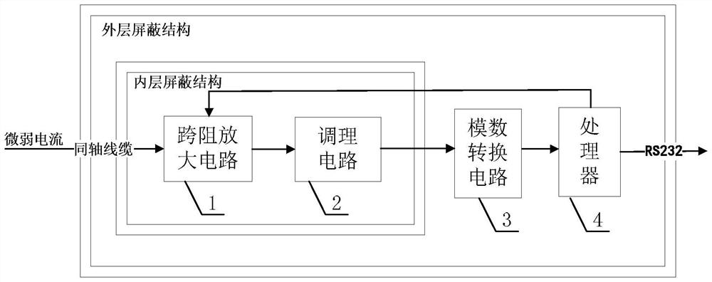
[0032] Specific implementation mode 1: refer to figure 1 and figure 2 Specifically describing this embodiment, a weak current detection device described in this embodiment includes: a transimpedance amplifier circuit 1 , a conditioning circuit 2 , an analog-to-digital conversion circuit 3 , a processor 4 , an inner shielding structure and an outer shielding structure.
[0033] The transimpedance amplifying circuit 1 and the conditioning circuit 2 are all located in the inner shielding structure, and the inner shielding structure, the analog-to-digital conversion circuit 3 and the processor 4 are all located in the outer shielding structure.
[0034] The amplified signal output end of the transimpedance amplifier circuit 1 is connected to the signal input end of the conditioning circuit 2, the conditioning signal output end of the conditioning circuit 2 is connected to the signal input end of the analog-to-digital conversion circuit 3, and the digital signal output end of the ...
specific Embodiment approach 2
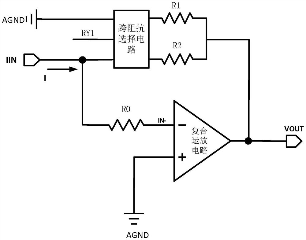
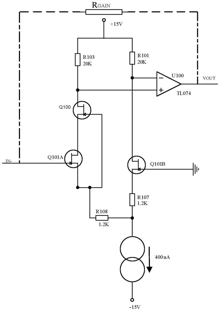
[0039] Specific implementation two: refer to image 3 and Figure 4 This embodiment is specifically described. This embodiment is a further description of the weak current detection device described in Embodiment 1. In this embodiment, the composite operational amplifier circuit includes: a field effect transistor Q100, a field effect transistor Q101A, a field effect transistor Q101A, a field effect transistor Q101A, a field effect transistor Effect tube Q101B, resistors R100~R108, resistor R113, polar capacitor CP100, capacitors C100~C103, diode CR100, diode CR101, amplifier U100 and constant current source circuit.
[0040] The gate of the field effect transistor Q101A is used as the inverting input terminal of the composite operational amplifier circuit. The source of the field effect transistor Q101A is connected to one end of the resistor R108 and the gate of the field effect transistor Q100 respectively. The source of the transistor Q100 and the drain of the FET Q100 ar...
specific Embodiment approach 3
[0045] Specific implementation mode three: refer to Figure 5 to Figure 8 This embodiment is described in detail. This embodiment is a further description of the weak current detection device described in Embodiment 1 or 2. In this embodiment, the transimpedance selection circuit includes a monostable double-contact relay and an NPN type relay. Transistor D1.
[0046] The 2-pin and 5-pin of the monostable double-contact relay are connected with one end of the gain resistor R2, and the 4-pin and 7-pin of the monostable double-contact relay are connected with one end of the gain resistor R1. The 6-pin of the contact relay is used as the micro-current input terminal of the transimpedance selection circuit, the 8-pin of the monostable double-contact relay is connected to the collector of the triode D1, and the base of the triode D1 is used as the range switching signal of the transimpedance selection circuit At the input end, the emitter of the triode D1 is connected to the power...
PUM
| Property | Measurement | Unit |
|---|---|---|
| Resistance | aaaaa | aaaaa |
| Resistance | aaaaa | aaaaa |
| Resistance | aaaaa | aaaaa |
Abstract
Description
Claims
Application Information
 - R&D
- Intellectual Property
- Life Sciences
- Materials
- Tech Scout
- Unparalleled Data Quality
- Higher Quality Content
- 60% Fewer Hallucinations
Browse by: Latest US Patents, China's latest patents, Technical Efficacy Thesaurus, Application Domain, Technology Topic, Popular Technical Reports.
© 2025 PatSnap. All rights reserved.Legal|Privacy policy|Modern Slavery Act Transparency Statement|Sitemap|About US| Contact US: help@patsnap.com