
Lubricating oil stirring device facilitating feeding

A stirring device and lubricating oil technology, which is applied to mixers with rotating stirring devices, mixer accessories, transportation and packaging, etc., can solve the problems of not effectively slowing down the speed of lubricating oil feeding, insufficient stirring and mixing of lubricating oil, and inability to Problems such as adding lubricating oil in batches to achieve superior performance, improve stirring efficiency, and avoid waste

Pending Publication Date: 2022-07-01
无锡惠中石油销售有限公司
View PDF0 Cites 0 Cited by
  • Summary
  • Abstract
  • Description
  • Claims
  • Application Information

AI Technical Summary

Problems solved by technology

[0006] Aiming at the deficiencies of the prior art, the present invention provides a lubricating oil stirring device that is convenient for feeding, which solves the problem that when the lubricating oil is unloaded, the lubricating oil cannot be put into the mixing box in batches, and at the same time, it cannot effectively slow down The speed of lubricating oil cutting, if the speed of lubricating oil cutting is too fast, too much lubricating oil will easily lead to the problem of uneven stirring of lubricating oil. In addition, when the lubricating oil is stirred and mixed in the mixing box, the inner wall of the mixing box cannot be mixed. The substance is scraped off, and the substance adheres to the inner wall, which may easily cause insufficient stirring and mixing of the lubricating oil, which increases the waste of lubricating oil

Method used


Image

  • Lubricating oil stirring device facilitating feeding
  • Lubricating oil stirring device facilitating feeding
  • Lubricating oil stirring device facilitating feeding

Examples


Embodiment Construction

[0023] The technical solutions in the embodiments of the present invention will be clearly and completely described below with reference to the accompanying drawings in the embodiments of the present invention. Obviously, the described embodiments are only a part of the embodiments of the present invention, rather than all the embodiments. Based on the embodiments of the present invention, all other embodiments obtained by those of ordinary skill in the art without creative efforts shall fall within the protection scope of the present invention.

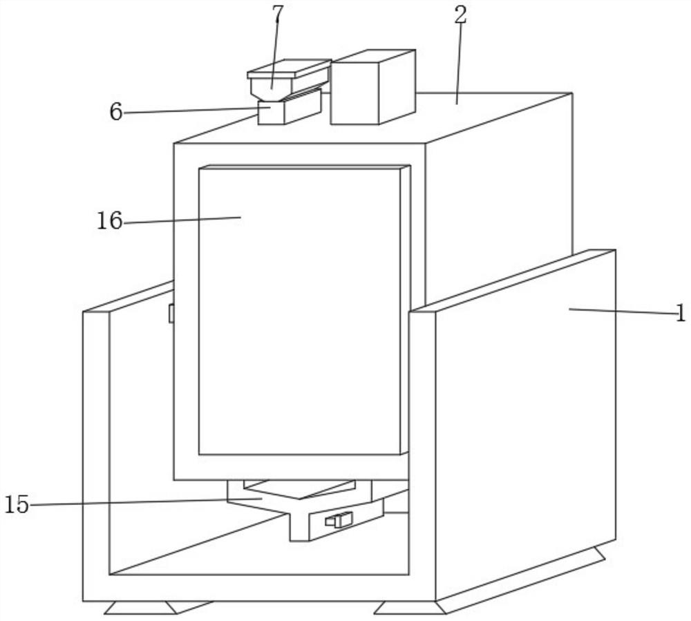
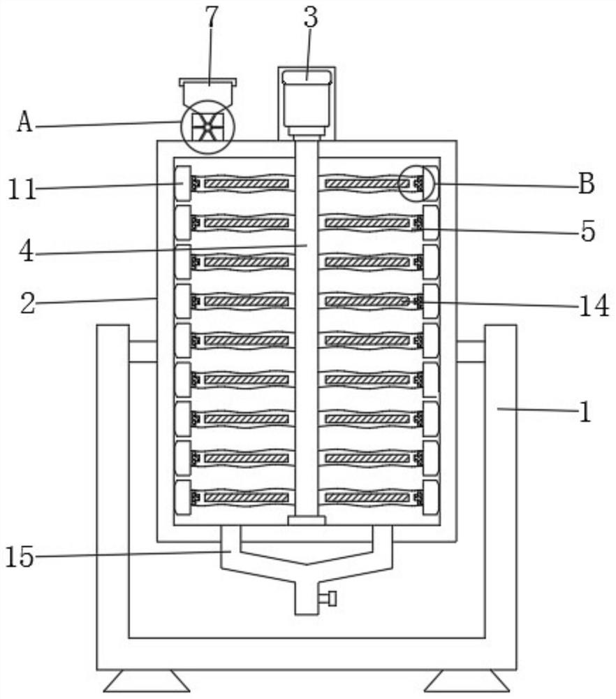
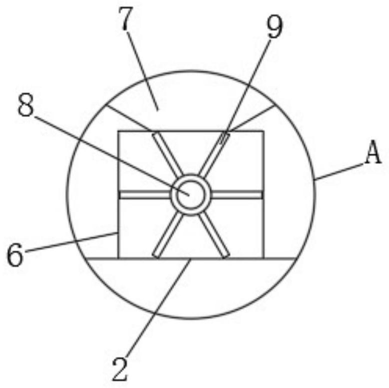
[0024] see Figure 1-4 , in this embodiment: a lubricating oil stirring device that is convenient for feeding, comprising a support frame 1, a stirring box 2 is arranged inside the support frame 1, a motor 3 is installed on the top of the stirring box 2, and the lower end of the motor 3 is located at the stirring The inside of the box 2 is provided with a driving rod 4, the outer wall of the driving rod 4 is provided with a stirring ...


PUM


Abstract

The invention belongs to the technical field of lubricating oil stirring devices, and particularly relates to a lubricating oil stirring device facilitating feeding, which comprises a support frame, a stirring box is arranged in the support frame, a motor is mounted at the top end of the stirring box, a driving rod is arranged at the lower end of the motor and located in the stirring box, and stirring blades are arranged on the outer surface wall of the driving rod. A discharging channel is arranged on one side of the motor, a feeding port is formed in the upper end of the discharging channel, a rotating rod is arranged in the discharging channel, a partition plate is arranged on the outer surface wall of the rotating rod, and a connecting block is arranged at one end of each stirring blade. The rotating rod and the partition plate are additionally arranged in the discharging channel, so that lubricating oil can be fed into the stirring box in batches, and meanwhile, the discharging speed of the lubricating oil can be effectively reduced; by additionally arranging the detachable scraping plate at one end of the stirring blade, substances on the inner wall of the stirring box can be scraped off by the scraping plate, so that the problem of insufficient stirring and mixing of lubricating oil due to the fact that the substances are adhered to the inner wall is avoided.

Description

technical field [0001] The invention relates to the technical field of lubricating oil stirring devices, in particular to a lubricating oil stirring device which is convenient for feeding. Background technique [0002] Lubricating oil is a liquid or semi-solid lubricant used in various types of automobiles and mechanical equipment to reduce friction and protect machinery and processed parts. It mainly plays the roles of lubrication, auxiliary cooling, rust prevention, cleaning, sealing and buffering; as long as it is It is applied between two objects in relative motion, and can reduce the friction and wear caused by the contact between the two objects, that is, lubricating oil. Lubricating oil is a technology-intensive product and is a complex mixture of hydrocarbons. , and its real performance is the combined effect of complex physical or chemical change processes. After adding additives to the base oil of lubricating oil, it is necessary to stir the base oil and additives ...

Claims


Application Information

Patent Timeline
Patent Type & Authority Applications(China)
IPC IPC(8): B01F27/90B01F27/091B01F27/191B01F35/50B01F35/71B01F101/39
Inventor 戴小龙
Owner 无锡惠中石油销售有限公司
Learn More