Supercharge Your Innovation With Domain-Expert AI Agents!

Internal rotational flow cross hole double-air-assisted ejector

A cross-hole and injector technology, applied in the direction of injection device, liquid injection device, etc., can solve the problems of poor fuel atomization effect and poor disturbance of the injector, improve the fluid mixing uniformity, reduce the spray particle size, and improve the Effects of mixing and jetting properties

Pending Publication Date: 2022-07-01
DALIAN UNIV OF TECH
View PDF12 Cites 0 Cited by
  • Summary
  • Abstract
  • Description
  • Claims
  • Application Information

AI Technical Summary

Problems solved by technology

[0005] In view of this, the present invention provides an internal swirl cross-hole double air-assisted injector, aiming to solve the problems of poor atomization effect of fuel injectors in the prior art, poor disturbance after mixing of various fluids, etc.

Method used


Image

  • Internal rotational flow cross hole double-air-assisted ejector
  • Internal rotational flow cross hole double-air-assisted ejector
  • Internal rotational flow cross hole double-air-assisted ejector

Examples


Embodiment 1

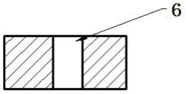
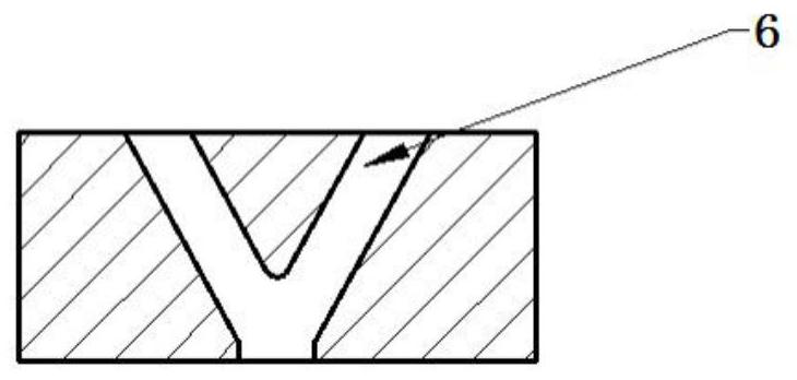
[0037] see Figure 1-14 , the embodiment of the present invention discloses an internal swirl cross-hole dual gas assisted injector, comprising: a main body 1, the main body 1 has a first cavity 2, a second cavity 3, a first channel 4, a second channel 5 and The third channel 6, the first cavity 2 is arranged on the first end face of the main body 1, the first cavity 2 is a blind hole arranged on the axis of the main body 1, the second cavity 3 is sleeved on the periphery of the first cavity 2, The first cavity 2 and the second cavity 3 are coaxially arranged, the side walls of the first cavity 2 and the second cavity 3 are communicated through the first channel 4, and the third channel 6 is arranged on the second end surface of the main body 1, And the third channel 6 communicates with the first cavity 2 , and the bottom end of the second cavity 3 communicates with the third channel 6 through the second channel 5 .

[0038] In the above embodiment, a plurality of first chann...

Embodiment 2

[0042] see Figure 15 , the rest of the structure is the same as the structure in Embodiment 1, the difference is that the setting method of the second channel 5 is different from that in Embodiment 1. In this embodiment, one end of the second channel 5 is communicated with the second cavity 3. Specifically Ground, one end of the second channel 5 is connected with the side wall of the second cavity 3, and the other end is communicated with the first cavity 2, the inclination angle of the second channel 5 is the same as the inclination angle of the third channel 6, and the second channel 5 is located in in the extension direction of the third channel 6 .


PUM


Abstract

The invention discloses an internal rotational flow cross hole double-air-assisted ejector which comprises a body, the body is provided with a first cavity, a second cavity, a first channel, a second channel and a third channel, the first cavity is arranged on the first end face of the body and is a blind hole formed in the axis of the body, the second cavity is arranged on the periphery of the first cavity in a sleeving mode, and the third channel is arranged on the second end face of the body. The first cavity and the second cavity are coaxially arranged, the side wall of the first cavity is communicated with the side wall of the second cavity through the first channel, the third channel is arranged on the second end face of the body and communicated with the first cavity, and the second cavity is communicated with the third channel through the second channel. The jet device has the beneficial effects that fluid is introduced into the first cavity and the second cavity respectively, then turbulence disturbance in the jet holes of the jet device can be enhanced, better mixing and jetting characteristics are obtained, meanwhile, the high-disturbance jet device enhances the solution atomization effect, the spray particle size is reduced by 25% or above under the same jetting pressure, and the spraying effect is improved. And the fluid evaporation, atomization and mixing efficiency is improved by more than 50%.

Description

technical field [0001] The invention relates to the technical field of ejectors, and more particularly to an internal swirl cross-hole double gas-assisted ejector. Background technique [0002] At present, the ejector is used in many kinds of spraying, spraying, oil spraying, sandblasting, spraying and other equipment, plays an important role, and is a very critical component that affects the effect of fluid atomization. Injectors are widely used in the industry, but still have the following shortcomings: [0003] For example: First, in the field of internal combustion engine in-cylinder fuel atomization, the atomization effect of fuel has a great influence on the fuel combustion effect, which directly affects the emission of pollutants. With the increasingly stringent national emission regulations, The requirements for fuel injectors are becoming more and more stringent; secondly, in order to reduce NOx emissions in the engine after-treatment system, a reducing agent is in...

Claims


Application Information

Patent Timeline
Patent Type & Authority Applications(China)
IPC IPC(8): B05B7/04
CPCB05B7/04
Inventor 隆武强田华崔靖晨田江平陈晓瑜赵成微于聪张振先礼博董东升
Owner DALIAN UNIV OF TECH
Features
  • R&D
  • Intellectual Property
  • Life Sciences
  • Materials
  • Tech Scout
  • Unparalleled Data Quality
  • Higher Quality Content
  • 60% Fewer Hallucinations
Learn More