Spot welding machine capable of adjusting spot welding angle for halogen lamp production and adjusting method

A halogen lamp, adjustable technology, applied in the direction of welding/welding/cutting items, welding equipment, resistance welding equipment, etc., can solve the problems of inconvenient welding needs, welding position deviation, adjustment of welding angle, etc., and achieve the effect of improving welding efficiency

Active Publication Date: 2022-07-01
宿迁启辉照明电器有限公司
View PDF8 Cites 0 Cited by
  • Summary
  • Abstract
  • Description
  • Claims
  • Application Information

AI Technical Summary

Problems solved by technology

[0002] Halogen lamps are lamps in which halogen gases such as iodine or bromine are injected into traditional incandescent bulbs, and spot welding machines are equipment for welding electrodes in the production process of halogen lamps. When spot welding machines are welding, it is not convenient to adjust the welding angle according to welding needs. , so during the halogen lamp welding operation, it is necessary to frequently adjust the welding position of the halogen lamp to be in direct alignment with the upper and lower electrodes of the spot welder, so as to realize the welding operation of the halogen lamp electrodes, but the way of welding operation by adjusting the halogen lamp, It is easy to cause deviation of the welding position, so a spot welding machine and adjustment method with adjustable spot welding angle for the production of halogen lamps are designed to solve the above problems

Method used


Image

  • Spot welding machine capable of adjusting spot welding angle for halogen lamp production and adjusting method
  • Spot welding machine capable of adjusting spot welding angle for halogen lamp production and adjusting method
  • Spot welding machine capable of adjusting spot welding angle for halogen lamp production and adjusting method

Examples


Embodiment 1

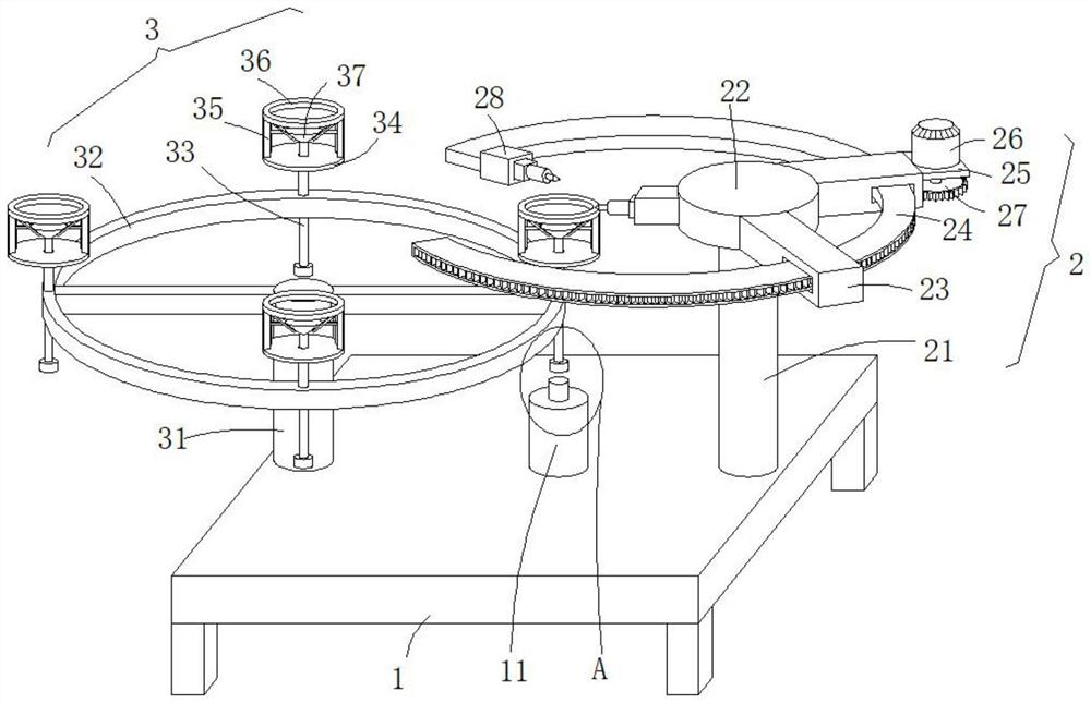
[0033] see Figure 1-3 , this embodiment provides a spot welding machine and an adjustment method with an adjustable welding angle for halogen lamp production, including a welding seat 1, a transmission mechanism 2 for installing the upper and lower electrodes of the spot welding machine, and a material loading mechanism 3 , the transmission mechanism 2 is arranged on the upper end side of the welding seat 1, and the welding seat 1 vacates the transmission mechanism 2 to adjust the spot welding positions of the upper electrode and the lower electrode of the spot welding machine to meet the requirements of the upper electrode and the lower electrode of the spot welding machine. Electrode precise spot welding requirements.

[0034]The transmission mechanism 2 includes a first column 21 and a transmission frame 24. The first column 21 is fixed on one side of the upper end of the welding seat 1 and a tray 22 is fixed at the top of the first column 21. The transmission frame 24 is ...

Embodiment 2

[0043] see figure 1 , figure 2 and Figure 4 , made further improvements on the basis of Example 1:

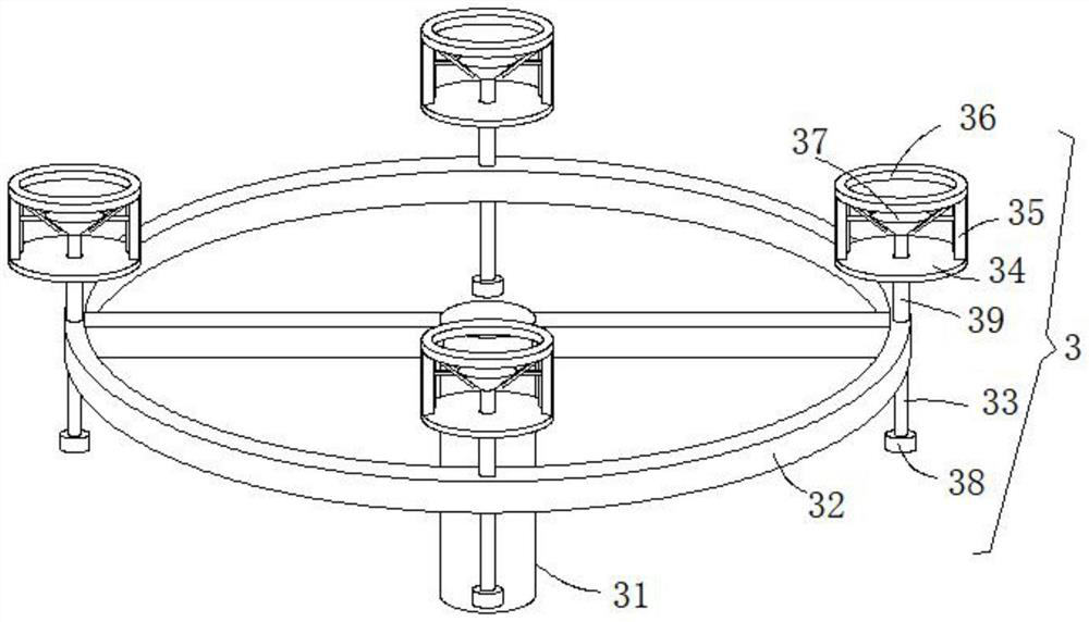
[0044] Prevent the halogen lamp on the support plate 34 from being easily separated from the support plate 34 by the centrifugal force generated by the rotation of the annular support frame 32 in the state without peripheral protection, which is easy to cause the halogen lamp to fall and break, and also affects the efficient welding operation of the halogen lamp. In order to prevent the halogen lamp from falling off the support plate 34 during the transmission process, two support rods 35 are symmetrically arranged on the upper end of the support plate 34 and a protective frame 36 is fixed between the top ends of the two support rods 35. The protective frame 36 is vacated and used as a protective fence. When the halogen lamp to be welded is placed on the support plate 34, the protective frame 36 is used to protect and support the periphery of the halogen lamp to prevent the...

Embodiment 3

[0048] see figure 1 , figure 2 , Figure 4 , Figure 5 , Image 6 , Figure 7 and Figure 8 , made further improvements on the basis of Example 2:

[0049] A support sleeve 39 is fixed at the bottom end of the support plate 34 , and the support sleeve 39 is fixed on the upper end surface of the annular support frame 32 , and the support plate 34 is stably supported on the upper end surface of the annular support frame 32 by the support sleeve 39 , to ensure that when the annular support frame 32 rotates with the second column 31 as the center, the support plate 34 can also make a circular motion with the second column 31 as the center, so as to realize the orderly transmission of the halogen lamp to be welded.

[0050] After the halogen lamp is welded, in order to facilitate taking out the halogen lamp from the protective frame 36, a guide rod 33 is slidably penetrated through the middle-shaped through hole in the support sleeve 39, and the top of the guide rod 33 slide...


PUM


Abstract

The invention discloses a spot welding machine capable of adjusting the spot welding angle for halogen lamp production and an adjusting method, and relates to the technical field of halogen lamp production welding, the spot welding machine comprises a welding seat, a transmission mechanism used for installing an upper electrode and a lower electrode of the spot welding machine and a material carrying mechanism, and the transmission mechanism comprises a first stand column and a transmission frame; the first stand column is fixed to one side of the upper end of the welding base, a tray is fixedly arranged at the top end of the first stand column, the transmission frame is of an arc-shaped structure, a feeding notch is formed between the head end and the tail end of the transmission frame, and the transmission frame is adjustably arranged on the outer side of the tray. The second stand column is rotationally arranged on the other side of the upper end of the welding base, and a plurality of supporting discs used for containing halogen lamps to be welded are arranged at the upper end of the annular supporting frame. The traditional mode that the upper electrode and the lower electrode of the spot welding machine are aligned by correcting the welding position of the halogen lamp is changed, the welding points of the halogen lamp can be accurately welded without adjusting the halogen lamp, and the welding efficiency of the halogen lamp is improved.

Description

technical field [0001] The invention relates to the technical field of halogen lamp production and welding, in particular to a spot welder and an adjustment method with an adjustable point welding angle for halogen lamp production. Background technique [0002] The halogen lamp is a lamp that injects halogen gas such as iodine or bromine into the traditional incandescent light bulb, and the spot welding machine is the equipment for the welding operation of the electrode in the production process of the halogen lamp. When the spot welding machine is welding, it is not convenient to adjust the welding angle according to the welding needs. Therefore, during the welding operation of the halogen lamp, it is necessary to frequently adjust the welding position of the halogen lamp to face the upper and lower electrodes of the spot welding machine, so as to realize the welding operation of the halogen lamp electrode, but the welding operation is carried out by adjusting the halogen la...

Claims


Application Information

Patent Timeline
Patent Type & Authority Applications(China)
IPC IPC(8): B23K11/11B23K11/36B23K101/36
CPCB23K11/11B23K11/36B23K2101/36Y02B20/00
Inventor 张明昊张启忠王中龙王晓莉李元元李明西李明利邓会明
Owner 宿迁启辉照明电器有限公司
Why Eureka
Try Eureka