
Optical fiber laser welding machine online monitoring system, application and optical fiber laser welding machine

A fiber laser and monitoring system technology, applied in the field of laser applications, can solve the problems of not being able to analyze the beam quality through spectral characteristics, and not being able to realize online monitoring

Pending Publication Date: 2022-07-01
武汉镧芯光电技术有限公司
View PDF1 Cites 0 Cited by
  • Summary
  • Abstract
  • Description
  • Claims
  • Application Information

AI Technical Summary

Problems solved by technology

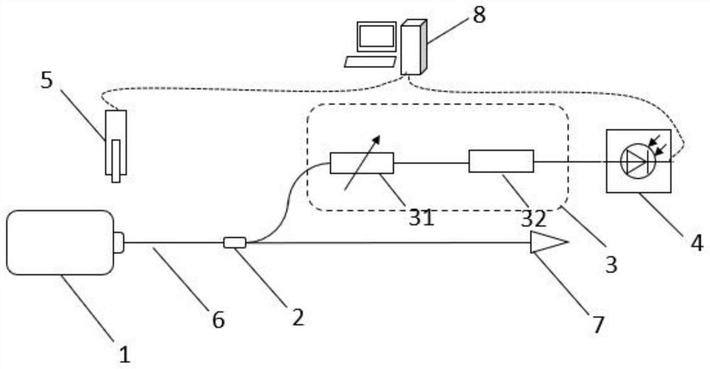
[0006] In view of the above defects or improvement needs of the prior art, the present invention provides an online monitoring system and application of an optical fiber laser welding machine and an optical fiber laser welding machine. The purpose is to monitor the output in real time by sampling the output laser The power change of the laser Raman light band can judge the output beam quality and working state of the laser welding machine, and realize online monitoring, so as to solve the problem that the existing technology can only detect the output energy density of the laser welding machine in the non-working state, and cannot realize online Technical problems of monitoring and not being able to analyze beam quality by spectral signature

Method used


Image

  • Optical fiber laser welding machine online monitoring system, application and optical fiber laser welding machine
  • Optical fiber laser welding machine online monitoring system, application and optical fiber laser welding machine
  • Optical fiber laser welding machine online monitoring system, application and optical fiber laser welding machine

Examples


Embodiment Construction

[0032] In order to make the objectives, technical solutions and advantages of the present invention clearer, the present invention will be further described in detail below with reference to the embodiments. It should be understood that the specific embodiments described herein are only used to explain the present invention, but not to limit the present invention. In addition, the technical features involved in the various embodiments of the present invention described below can be combined with each other as long as they do not conflict with each other.

[0033] The welding effect of the fiber laser welding machine is unstable, which is not only related to the output energy of the laser, but also related to the output spectrum of the fiber laser. There are several factors in a fiber laser welding machine that affect the spectrum of the final output. The more obvious influencing factors are: the grating in the fiber laser is affected by temperature, causing spectral drift; th...


PUM


Abstract

The invention discloses an optical fiber laser welding machine online monitoring system, application and an optical fiber laser welding machine. The system comprises an optical splitter, a detection light path and a photoelectric detector, the optical splitter is connected with a laser transmission optical fiber of the optical fiber laser welding machine or is arranged in a welding head light path, and is used for sampling output laser and inputting detection light obtained by sampling into a detection light path; the detection light path at least comprises a filter for selecting a detection wave band; the filter is used for selecting an optical signal of a Raman optical band; and the photoelectric detector is connected with the output of the detection light path and is used for detecting the optical power of the detection wave band output by the detection light path. The system is applied to online monitoring of the high-power continuous laser welding machine, optical power signals of Raman optical bands are monitored in real time, full-band output spectrum analysis is replaced, and laser output quality can be accurately judged while real-time response and online monitoring are achieved, so that the working state of the laser welding machine is judged.

Description

technical field [0001] The invention belongs to the field of laser application, and more particularly, relates to an on-line monitoring system and application of a fiber laser welding machine and a fiber laser welding machine. Background technique [0002] The fiber laser welding machine uses the fiber laser as the laser source, and emits a high-power light spot through the focusing lens group, which is irradiated on the processing material to realize welding. Fiber laser welding machine has the advantages of small size, compact structure, high reliability, good beam quality, large penetration and small deformation, and has broad industrial application prospects. [0003] The welding effect of the fiber laser welding machine is determined by the output spot quality of the fiber laser. The quality of the output spot of the fiber laser is unstable, including the decrease of the spot brightness and the periodic change of the energy during the baking process. The output stabil...

Claims


Application Information

Patent Timeline
IPC IPC(8): B23K26/70B23K26/21
CPCB23K26/707B23K26/21B23K26/70
Inventor 杨思美李涛王银红陈宁李小涛
Owner 武汉镧芯光电技术有限公司
Learn More