Arrangement device for electronic component packaging

A technology for electronic components and sorting devices, which is applied in the field of sorting devices for packaging electronic components, and can solve problems such as low work efficiency and physical exertion

Inactive Publication Date: 2022-07-01
深圳市顺博兴电子有限公司
View PDF0 Cites 0 Cited by
  • Summary
  • Abstract
  • Description
  • Claims
  • Application Information

AI Technical Summary

Problems solved by technology

[0004] In order to overcome the shortcomings of labor-intensive manual sorting of electronic components, resulting in low work efficiency, the purpose of the present invention is to provide a time-saving and labor-saving sorting device for packaging electronic components

Method used


Image

  • Arrangement device for electronic component packaging
  • Arrangement device for electronic component packaging
  • Arrangement device for electronic component packaging

Examples


Embodiment 1

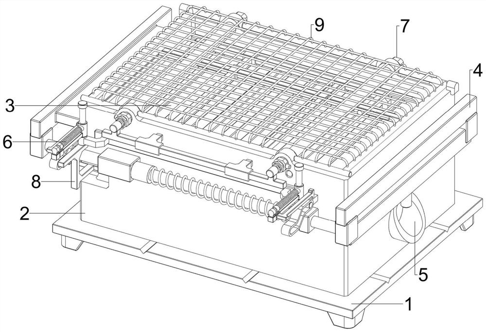
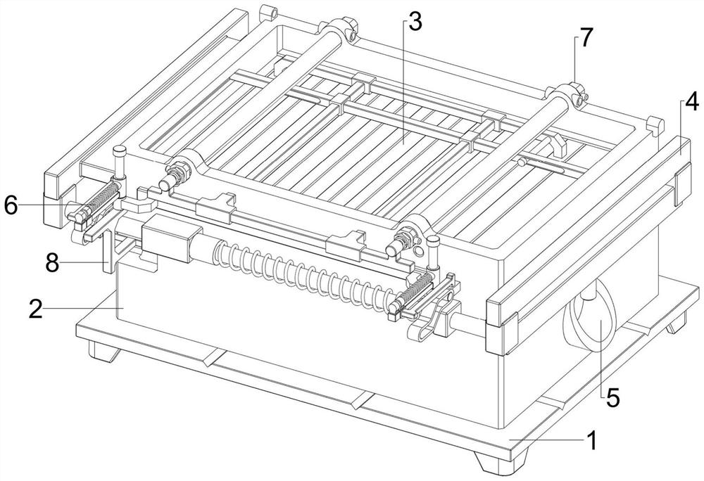
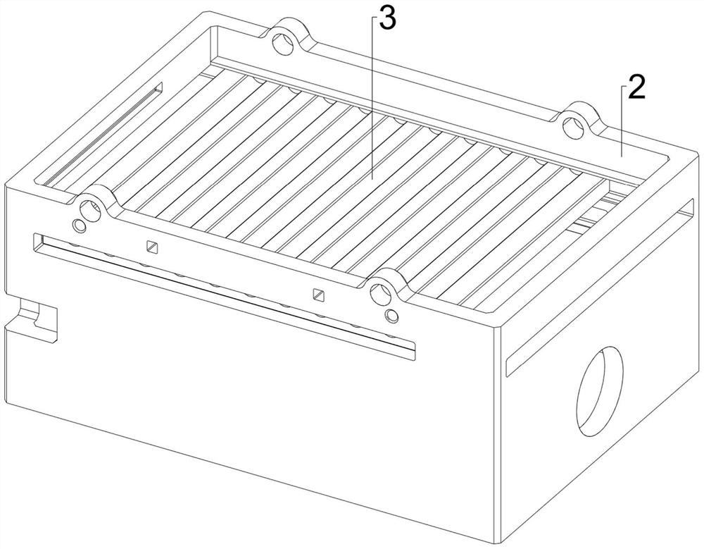
[0037] A finishing device for packaging electronic components, refer to Figure 1-Figure 7 , including a base 1, a frame body 2, a monolithic plate 3, a clamping mechanism 4 and a shaking mechanism 5. The top of the base 1 is provided with a frame body 2, and the inner upper part of the frame body 2 is slidably provided with a monolithic plate 3. The plate 3 is spaced with strip-shaped grooves. When the monolithic plate 3 reciprocates left and right, the electronic components can be shaken and arranged. The upper part of the frame body 2 is provided with a clamping mechanism 4, and the inner right part of the frame body 2 is provided with Shake mechanism 5.

[0038] refer to figure 1 , figure 2 , Figure 4 and Figure 5 , the clamping mechanism 4 includes a first guide sleeve 41, a second guide sleeve 42, a sliding rod 43, a first spring 44 and a splint 45, and the first guide sleeve 41 is welded to the front and rear left upper parts of the frame body 2. A second guide ...

Embodiment 2

[0042] On the basis of Example 1, refer to figure 1 , figure 2 , Figure 11 and Figure 12 , and also includes a withdrawal mechanism 7, the withdrawal mechanism 7 includes a first connecting rod 71, an electric push rod 72, a support rod 73, a second connecting rod 74, a pull rod 75 and a limit rod 76, the top of the monolithic plate 3 The rear side is welded with a first connecting rod 71 , the left and right sides of the upper part of the frame body 2 are bolted with electric push rods 72 , the inner upper part of the frame body 2 is slidably provided with a support rod 73 , and the support rod 73 is located above the monolithic plate 3 . A second connecting rod 74 is provided between the front sides of the telescopic rods of the electric push rod 72. The second connecting rod 74 is symmetrically provided with a pulling rod 75. The rear part of the pulling rod 75 is slidably connected with the first connecting rod 71. The pulling rod 75 They are all slidably connected t...


PUM


Abstract

The invention relates to an arrangement device, in particular to an arrangement device for electronic component packaging. The invention aims to provide a time-saving and labor-saving arrangement device for electronic component packaging. The arrangement device for electronic component packaging comprises a base, a frame body, an arrangement plate, a clamping mechanism and the like, the frame body is arranged at the top of the base, and the arrangement plate used for conducting shaking arrangement on electronic components is arranged on the upper portion of the inner side of the frame body in a sliding mode. A clamping mechanism used for driving the material arranging plate to reciprocate left and right is arranged on the upper portion of the frame body. According to the electronic component sorting device, the motor serves as driving force, the cam can be driven to rotate, then the sorting plate can be driven to do left-right reciprocating motion under cooperation of the first spring, so that electronic components are shaken, the electronic components can be arranged in the strip-shaped grooves in the sorting plate in order, sorting work is completed, and time and labor are saved.

Description

technical field [0001] The invention relates to a sorting device, in particular to a sorting device for packaging electronic components. Background technique [0002] Before the electronic components are packaged, it is generally necessary to manually organize the electronic components, so as to facilitate the subsequent packaging work and not be very chaotic. [0003] At present, there are generally two methods for manually sorting electronic components. The first method is to manually sort electronic components and then arrange them. However, electronic components are small in size, and manual operation is inconvenient. It is easy to hurt your hands, resulting in low work efficiency. The second method is to put a batch of electronic components on the sieve plate with grooves, and then shake the sieve plate back and forth to make the electronic components neatly arranged. In the groove of the sieve plate, but this method consumes people's physical strength. Therefore, a ti...

Claims


Application Information

Patent Timeline
Patent Type & Authority Applications(China)
IPC IPC(8): B65B35/56B65B35/40B65B15/04
CPCB65B35/56B65B35/40B65B15/04
Inventor 邱焕钟
Owner 深圳市顺博兴电子有限公司
Why Eureka
Try Eureka