CVD (Chemical Vapor Deposition) workbench rotating device and CVD device

A technology of rotating device and workbench, which is applied in the direction of metal material coating process, coating, gaseous chemical plating, etc., and can solve the problems of inconsistent coating thickness and so on

Active Publication Date: 2022-07-01
广州志橙半导体有限公司
View PDF2 Cites 0 Cited by
  • Summary
  • Abstract
  • Description
  • Claims
  • Application Information

AI Technical Summary

Problems solved by technology

This results in inconsistent coating

Method used


Image

  • CVD (Chemical Vapor Deposition) workbench rotating device and CVD device
  • CVD (Chemical Vapor Deposition) workbench rotating device and CVD device
  • CVD (Chemical Vapor Deposition) workbench rotating device and CVD device

Examples


Embodiment 1

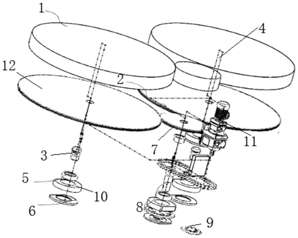
[0070] The embodiment of the present invention provides a CVD table rotating device, such as figure 1 shown, including:

[0071] The active rotating table 2 is rotatably connected to the furnace body through the main drive shaft 4; the above-mentioned active rotating table 2 is designed according to different furnace bodies. Optionally, for different product parts, it is also possible to change the installation position of the rotary table, for example, when facing long strips, the table can be installed on both sides of the furnace body to make two worktables work. The synchronous rotation of the table is used together to achieve the purpose of uniform coating on both sides of the workpiece at one time. Optionally, the whole rotary table can be raised and lowered by adding a screw nut.

[0072] One end of the sprocket drive shaft 8 extends into the furnace body and is connected to the main drive shaft 4, and the other end of the sprocket drive shaft 8 is located outside the ...

Embodiment 2

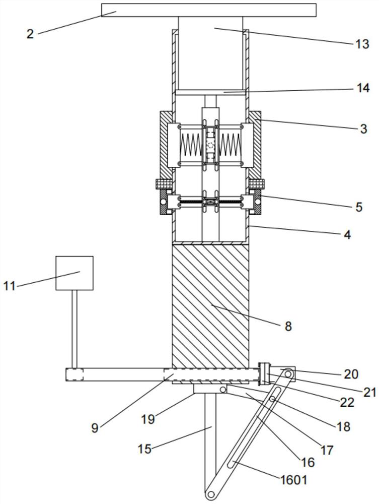
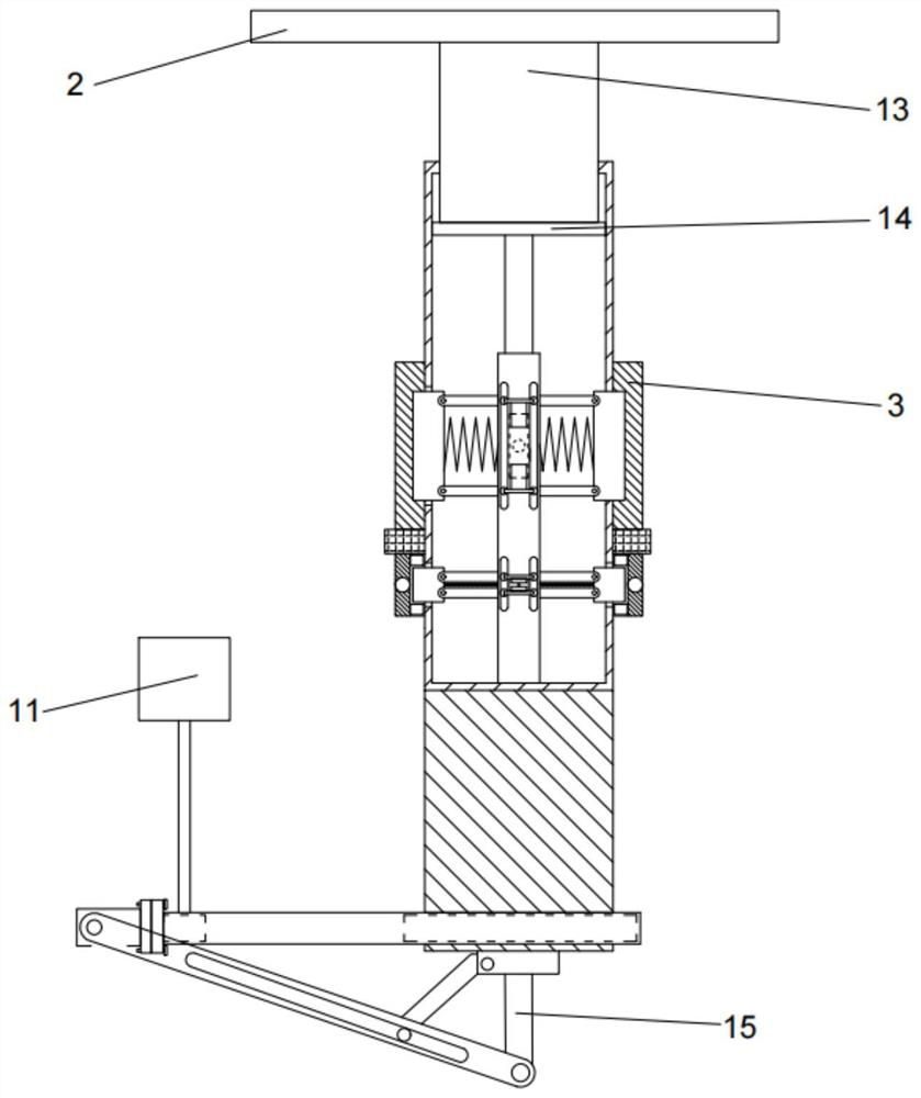
[0094] On the basis of Example 1, as figure 2 As shown in -5, the main drive shaft 4 is provided with an auxiliary mechanism, and the auxiliary mechanism includes:

[0095] Working cavity 401, the working cavity 401 is arranged inside the main drive shaft 4, the left and right ends of the working cavity 401 are symmetrically provided with a connecting hole 402, a connecting hole 2 403, and the connecting hole 2 403 and the connecting hole The first 402 is distributed up and down, and the working chamber 401 communicates with the outside world through the first connecting hole 402 and the second connecting hole 403;

[0096] The fixing block 23, the fixing block 23 is fixedly arranged in the middle of the lower end of the working chamber 401, the upper and lower sides of the fixing block 23 are respectively provided with a connecting assembly, the connecting assembly includes two chute-1 2301, the Two sliding grooves 1 2301 are symmetrically arranged on the left and right sid...

Embodiment 3

[0105] On the basis of embodiment 1 or 2, also include:

[0106] The gear sleeves inlaid on the outside of the active rotary table 2 and the driven rotary table 12 are exactly the same;

[0107] Load cell 1: A weighing layer is set on the upper end of the driven rotary table 12, and a weighing cell 1 is arranged inside the weighing layer, and the weighing sensor 1 is used to detect the upper end of the driven rotary table 12. the total weight of the connector;

[0108] Two weighing sensors: a weighing layer is arranged on the upper end of the active rotating table 2, and a second weighing sensor is arranged inside the weighing layer, and the second weighing sensor is used to detect the connection of the upper end of the active rotating table 2 the total weight of the piece;

[0109] Distance sensor 1: The distance sensor is arranged at the center of the upper end of the driven rotary table 12, and is used to detect the distance between the connecting piece on the upper end o...


PUM


Abstract

The invention provides a CVD workbench rotating device and a CVD device.The CVD workbench rotating device comprises a rotating workbench, the rotating workbench comprises a driving rotating workbench body and a driven rotating workbench body, gear sleeves are embedded in the outer side of the driving rotating workbench body and the outer side of the driven rotating workbench body, and the driving rotating workbench body and the driven rotating workbench body are connected through a rotating shaft; the gear sleeve of the driving rotary workbench is meshed with the gear sleeve of the driven rotary workbench; the driving rotary workbench is rotationally connected into the furnace body through a main transmission shaft, and the driving transmission shaft is connected with a driving mechanism. The tool jig frame is used for solving the problem that a workpiece is fixed relative to an air field, and the tool jig frame placed on the rotary workbench serves as a fan blade in the rotating process to stir the original air field in a cavity, so that the original air field can better form a relatively stable and diffused air field in the cavity. And the workpiece rotates at a certain speed in the gas field and is in full contact with the reaction gas, so that the reaction gas has enough use efficiency.

Description

technical field [0001] The present invention relates to the technical field of CVD devices, in particular to a CVD table rotating device and a CVD device. Background technique [0002] The existing CVD (Chemical Vapor Deposition) in the domestic market is divided into shield lifting type, bottom lifting type, vertical upper opening type, horizontal front opening type and other types according to the structure of the furnace body. It is found that they all have the same drawbacks, that is, the CVD gas reaction efficiency is low, the thickness of the coating is uneven, and the production cost is generally high. [0003] By analyzing the generation principle and monitoring the generation state, we found that the reason for restricting the quality of product generation is that the product (part) is in a fixed position within the range of the reaction gas field, while the furnace body is a regulated reaction gas, which is always only the gas that is in contact with the surface of...

Claims


Application Information

Patent Timeline
IPC IPC(8): C23C16/458C23C16/52
CPCC23C16/4581C23C16/4584C23C16/4586C23C16/52
Inventor 孙利朱佰喜薛抗美蒋彪杨伟峰
Owner 广州志橙半导体有限公司
Why Eureka
Try Eureka