Tube and wire driving device of vascular intervention surgical robot

A driving device and interventional surgery technology, applied in the field of medical equipment, can solve problems such as difficult control, no obvious and effective solution, and inconvenient installation of long and straight consumables, so as to enhance operability, improve operability, The effect of simplifying the clamping process

Pending Publication Date: 2022-07-05
易度河北机器人科技有限公司
View PDF1 Cites 1 Cited by
  • Summary
  • Abstract
  • Description
  • Claims
  • Application Information

AI Technical Summary

Problems solved by technology

[0002] In the field of existing interventional surgical robots, in the driving process of long straight consumables (including but not limited to: catheters, guide wires, balloons, stents, etc.), linear motion and rotational motion are mostly driven and controlled separately. In the application, there are problems such as inconvenient installation and difficult control of long and straight consumables, and existing solutions are used in catheters (including: support catheters, intermediate catheters, microcatheters, etc.), guide wires (including: loach guide wires, balloons, stents, etc.) , micro guide wire, etc.), there is no obvious and effective solution, resulting in a certain technical bottleneck in the clinical promotion of this technology

Method used


Image

  • Tube and wire driving device of vascular intervention surgical robot
  • Tube and wire driving device of vascular intervention surgical robot
  • Tube and wire driving device of vascular intervention surgical robot

Examples


Embodiment Construction

[0038] In order to achieve the above objects and effects, the technical means and structures adopted in the present invention will be described in detail with reference to the accompanying drawings with regard to the features and functions of the preferred embodiments of the present invention.

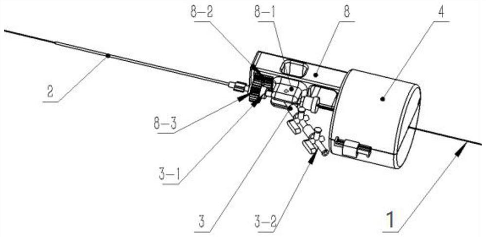
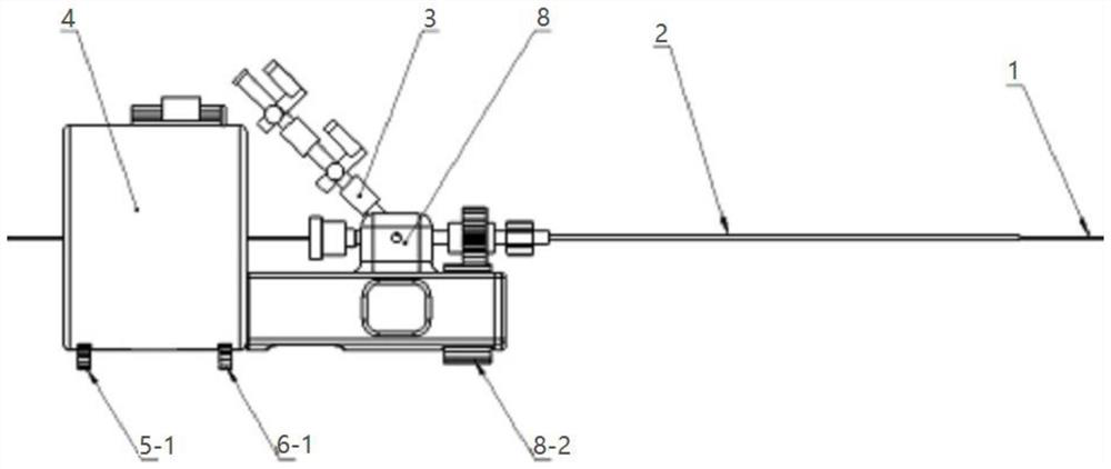
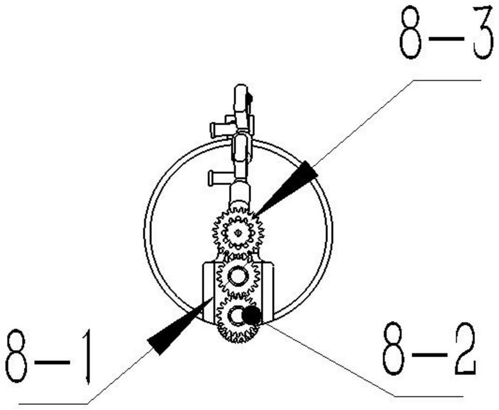
[0039] like Figure 1-10 As shown, the present invention provides a tube and wire driving device for a vascular interventional surgery robot, including a guide wire driving device and a catheter driving device 8, and the catheter driving device 8 is installed on one side of the guiding wire driving device, The guide wire driving device includes a sterile isolation housing 4, a loading support mechanism 7, a rotary motion mechanism 5 and a linear motion mechanism 6; wherein, the loading support mechanism 7, the rotary motion mechanism 5 and the linear motion mechanism 6 are all installed inside the aseptic isolation shell 4;

[0040]The linear running mechanism 6 includes a linear driv...


PUM


Abstract

The invention relates to a tube and wire driving device of a vascular intervention surgical robot, and relates to the technical field of medical instruments. Comprising a guide wire driving device and a catheter driving device, and the guide wire driving device comprises a sterile isolation shell, a loading supporting mechanism, a rotary movement mechanism and a linear operation mechanism; the loading support mechanism, the rotary motion mechanism and the linear operation mechanism are all mounted in the sterile isolation shell; the linear running mechanism comprises a linear driving device, a transmission device and a long and straight consumable driving wheel set, the end, located on the outer side of the loading supporting mechanism, of the transmission device is in transmission connection with the linear driving device, and the end, located in the loading supporting mechanism, of the transmission device is in transmission connection with the long and straight consumable driving wheel set; the rotary movement mechanism is installed at the end, away from the linear driving device, of the loading supporting mechanism. The long-distance collaborative delivery of the catheter and the guide wire can be completed; the operability, the safety and the usability of the minimally invasive vascular interventional operation assisted by the robot are improved.

Description

technical field [0001] The invention relates to the technical field of medical devices, in particular to a tube and wire driving device of a vascular interventional surgery robot. Background technique [0002] In the field of existing interventional surgical robots, in the existing solutions, in the driving process of long and straight consumables (including but not limited to: catheters, guide wires, balloons, stents, etc.), linear motion and rotational motion are mostly controlled separately. In the application, there are problems such as inconvenient installation and difficult control of long and straight consumables, and the existing solutions include catheters (including: support catheters, intermediate catheters, microcatheters, etc.), guide wires (including: loach guide wires, balloons, stents, etc.). There is no obvious and effective solution for the collaborative control direction of , micro guide wire, etc., resulting in a certain technical bottleneck in the clinic...

Claims


Application Information

Patent Timeline
IPC IPC(8): A61B34/30A61M25/01A61M25/09H02K7/06H02K7/10H02K7/116
CPCA61B34/30A61M25/0116A61M25/09041H02K7/10H02K7/116H02K7/06A61B2034/301A61B2034/303
Inventor 史文宝
Owner 易度河北机器人科技有限公司
Why Eureka
Try Eureka