Metal cutting device for machining center and working method of metal cutting device

A metal cutting and machining center technology, applied in metal processing equipment, metal processing machinery parts, manufacturing tools, etc., can solve the problem of inability to separate chips from cooling liquid, recycling of cooling liquid and chips, and effective treatment of cooling liquid and other issues to achieve the effect of improving quality inspection efficiency, saving costs, and improving product quality

Active Publication Date: 2022-07-05
XIANGNAN UNIV
View PDF16 Cites 0 Cited by
  • Summary
  • Abstract
  • Description
  • Claims
  • Application Information

AI Technical Summary

Problems solved by technology

However, the existing metal cutting processing devices cannot effectively treat the cooling liquid used for cooling when they are working, so that the chips and the cooling liquid cannot be separated, and the cooling liquid and the chips cannot be recycled separately.

Method used


Image

  • Metal cutting device for machining center and working method of metal cutting device
  • Metal cutting device for machining center and working method of metal cutting device
  • Metal cutting device for machining center and working method of metal cutting device

Examples


Embodiment 1

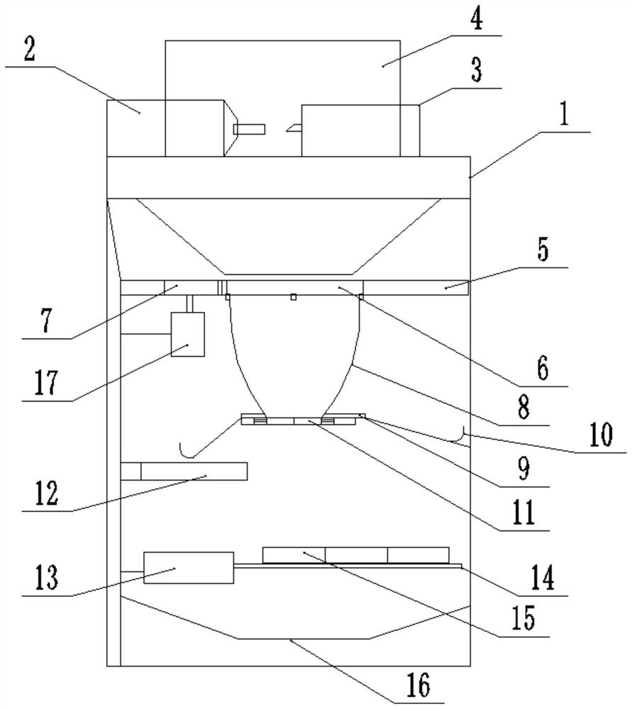
[0055] like Figure 1-3 As shown, a metal cutting device for a machining center includes a cutting mechanism, a collecting mechanism, and a filtering mechanism; wherein:

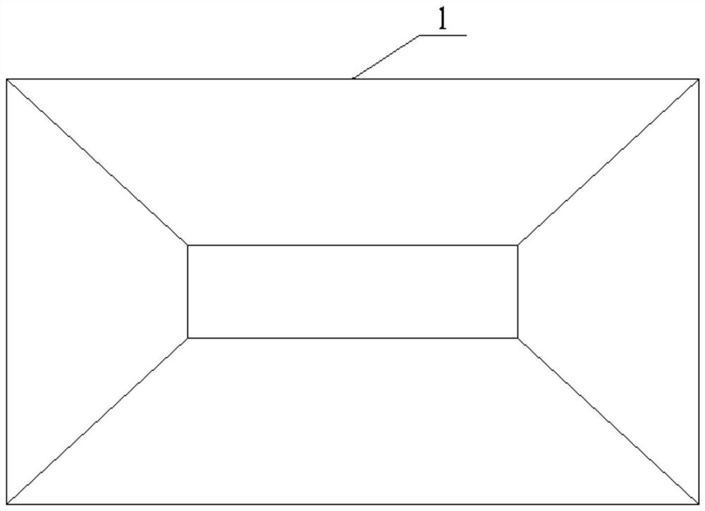
[0056] The cutting mechanism includes a frame 1, the middle of the frame 1 is a hollow structure, and the top of the frame 1 is provided with two symmetrical sliding rails along the length direction;

[0057] The clamping pile head 2 is fixedly installed on one side of the top of the frame 1, and the end of the clamping pile head 2 is provided with a chuck for clamping the workpiece;

[0058] The cutting pile head 3 is slidably installed on the top of the frame 1, and the cutting pile head 3 is provided with a cutting tool and a coolant nozzle; the coolant nozzle is aligned with the position where the cutting occurs, and is used for cooling the tool;

[0059] Protective cover 4, the protective cover 4 is in the shape of a long strip and is slidably connected to the slide rail. The protective cover 4 covers ...

Embodiment 2

[0080] In order to better understand the working principle or working process of the metal cutting device for a machining center provided in Embodiment 1, the working method of the metal cutting device for a machining center is described in detail in Embodiment 2.

[0081] Specifically, the specific steps of the working method of the metal cutting device for a machining center are as follows;

[0082] S1, load the workpiece, fix the workpiece to be cut on the clamping pile head 2, fix the tool on the cutting pile head 3, and adjust the position of the tool and the workpiece to facilitate cutting;

[0083] S2, adjust the position of the protective cover 4, slide the position of the protective cover 4 along the slide rail, and cover the cutting position;

[0084] S3, start the equipment to cut the workpiece, and start the coolant at the same time to cool down during cutting; the chips generated during cutting enter the filter mechanism along the conical funnel,


PUM


Abstract

The invention belongs to the technical field of metal cutting, and particularly relates to a metal cutting device for a machining center and a working method.The metal cutting device comprises a cutting mechanism, a collecting mechanism and a filtering mechanism, the cutting mechanism comprises a rack, the middle of the rack is of a hollow structure, and two symmetrical sliding rails are arranged on the top of the rack in the length direction; by means of the device, environmental pollution can be avoided, cooling liquid and chippings can be recycled and treated conveniently, and therefore the cost is saved; and in addition, defective products or defective products of corresponding batches can be quickly found for key screening, so that the quality inspection efficiency is effectively improved.

Description

technical field [0001] The invention belongs to the technical field of metal cutting, and particularly relates to a metal cutting device for a machining center and a working method thereof. Background technique [0002] The metal cutting processing device is a cutting tool with a cutting edge that is harder than the workpiece to cut off the excess metal layer on the blank (or blank) to obtain a workpiece with a specified size, geometry and surface quality. Processing method, cutting During processing, the surface of the workpiece is processed by the relative movement of the cutting tool and the workpiece; when the metal cutting device is cutting, a large amount of debris will be generated, and the debris needs to be collected and processed uniformly to save costs and avoid debris scattering The surrounding affects the environment. [0003] The popularity of metal cutting devices (such as CNC machine tools) has greatly improved the cutting efficiency. Usually, the workpiece ...

Claims


Application Information

Patent Timeline
Patent Type & Authority Applications(China)
IPC IPC(8): B23Q11/00B23Q11/08B23Q11/10B23Q17/00
CPCB23Q11/08B23Q11/1069B23Q11/0042B23Q17/00Y02P70/10
Inventor 廖勇彭乘风李翔
Owner XIANGNAN UNIV
Why Eureka
Try Eureka