Pipeline adjusting device of respirator for pulmonary intensive care unit

An intensive care unit and adjustment device technology, applied in the field of medical equipment, can solve the problems of inconvenient use and inability to achieve adjustment of pipelines, and achieve the effect of preventing bending

Inactive Publication Date: 2022-07-08
SHANGHAI PULMONARY HOSPITAL
View PDF0 Cites 0 Cited by
  • Summary
  • Abstract
  • Description
  • Claims
  • Application Information

AI Technical Summary

Problems solved by technology

[0003] At present, the length of the air delivery pipeline of the ventilator is often fixed and cannot be adjusted. In the actual use process, it is often inconvenient to use because the pipelin...

Method used


Image

  • Pipeline adjusting device of respirator for pulmonary intensive care unit
  • Pipeline adjusting device of respirator for pulmonary intensive care unit
  • Pipeline adjusting device of respirator for pulmonary intensive care unit

Examples


Embodiment 1

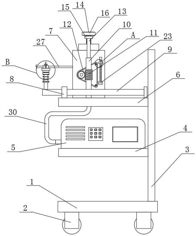
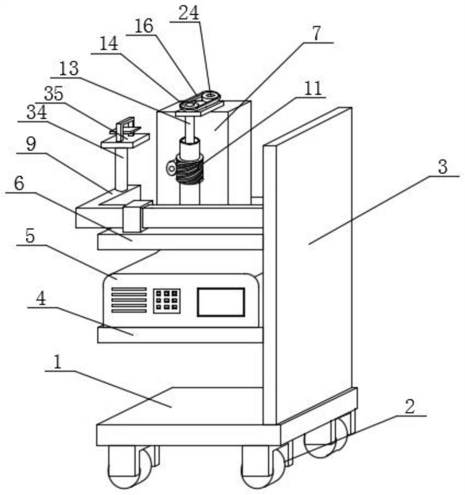
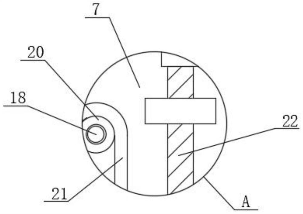
[0037] refer to Figure 1-12 In this embodiment, a pipeline adjustment device for a ventilator used in a pulmonary intensive care unit is proposed, which includes a base 1, and wheels 2 are installed on the four corners of the bottom of the base 1, and the setting of the wheels 2 can facilitate the movement of the device, In actual use, it is convenient. The vertical plate 3 is fixedly installed on the right side of the top of the base 1, and the supporting plate 4 is fixedly installed on the left side of the vertical plate 3. The supporting plate 4 can support the ventilator 5. The supporting plate The ventilator 5 is fixedly installed on the top of 4, and the support plate 6 is fixedly installed on the left top of the vertical plate 3. The support plate 6 can support the L-shaped rod 9 and the installation box 7, and the top of the support plate 6 is fixedly installed with a support plate 6. Installation box 7, a winding assembly is connected in the installation box 7, the t...

Embodiment 2

[0044] On the basis of the first embodiment, this embodiment is different in that: figure 1 and attached figure 2 , the support assembly includes an L-shaped rod 9, a support ring 8, a rotating shaft 34, a fixed plate 35, a clamping member, a gear member and a positioning member, the support ring 8 is fixedly installed on the top left side of the support plate 6, and the support ring 8 can be set to The L-shaped rod 9 is slidably supported. The L-shaped rod 9 penetrates through the support ring 8 and is slidably connected to the inner wall of the support ring 8. The L-shaped rod 9 can be provided to facilitate sliding support for the clamping member, so as to facilitate the clamping The position of the component is adjusted, the rotating shaft 34 is fixedly installed on the top left side of the L-shaped rod 9, and the rotating shaft 34 can be set to rotate and support the fixed plate 35, and can install and support the positioning member, so as to facilitate the fixed plate 3...


PUM


Abstract

The invention belongs to the technical field of medical instruments, particularly relates to a pipeline adjusting device of a breathing machine for an intensive care unit of the lung department, and aims to solve the problems that the length of a gas conveying pipeline of an existing breathing machine is always constant, adjustment cannot be achieved, and in the actual use process, use is inconvenient due to the fact that the pipeline is too long or too short. According to the scheme, the device comprises a base, wheels are installed at the four corners of the bottom of the base, a vertical plate is fixedly installed on the right side of the top of the base, a supporting plate is fixedly installed on the left side of the vertical plate, a breathing machine is fixedly installed on the top of the supporting plate, and a supporting plate is fixedly installed on the top of the left side of the vertical plate; according to the breathing machine, the length of a pipeline connected to the breathing machine can be conveniently adjusted, so that the breathing machine can be conveniently matched with a patient during breathing treatment of the patient, meanwhile, the pipeline can be stably supported, stable gas conveying can be guaranteed, and the breathing machine has good use convenience during use.

Description

technical field [0001] The invention relates to the technical field of medical devices, in particular to a pipeline adjustment device for a ventilator used in a pulmonary intensive care unit. Background technique [0002] In modern clinical medicine, ventilator, as an effective means to artificially replace the function of spontaneous ventilation, has been widely used in respiratory failure caused by various reasons, anesthesia and respiratory management during major surgery, respiratory support treatment and emergency resuscitation. It occupies a very important position in the field of modern medicine. A ventilator is a vital medical device that can prevent and treat respiratory failure, reduce complications, and save and prolong patients' lives. [0003] At present, the length of the air delivery pipeline of the ventilator is often fixed and cannot be adjusted. In the actual use process, it is often inconvenient to use because the pipeline is too long or too short. The p...

Claims


Application Information

Patent Timeline
IPC IPC(8): A61M16/00A61M16/08
CPCA61M16/0003A61M16/08A61M16/0816A61M2209/082A61M2209/084
Inventor 荆晓华
Owner SHANGHAI PULMONARY HOSPITAL
Why Eureka
Try Eureka