Hole making device

A hole-making device and placing table technology, applied in positioning devices, manufacturing tools, boring/drilling and other directions, can solve the problems of dead corners in the operating range of the drilling mechanism, wear and scratches on the surface of parts, and reduce the flexibility of the device. Flexible and stable drilling, increasing accuracy, and improving the effect of drilling quality

Pending Publication Date: 2022-07-08
XI'AN AIRCRAFT INTERNATIONAL
View PDF9 Cites 0 Cited by
  • Summary
  • Abstract
  • Description
  • Claims
  • Application Information

AI Technical Summary

Problems solved by technology

[0003] Similar hole-making devices in the prior art still have the following disadvantages: the positioning operation of the parts during hole making is relatively simple, and the positioning cannot be applied to parts with different shapes for stable positioning, and the positioning operation will cause wear and scratches on the surface of the parts At the same time, there is a dead angle in the operating range of the drilling mechanism, which reduces the flexibility of the device; in addition, the debris generated during drilling will splash on the table, which is inconvenient to clean

Method used


Image

  • Hole making device
  • Hole making device
  • Hole making device

Examples


Embodiment Construction

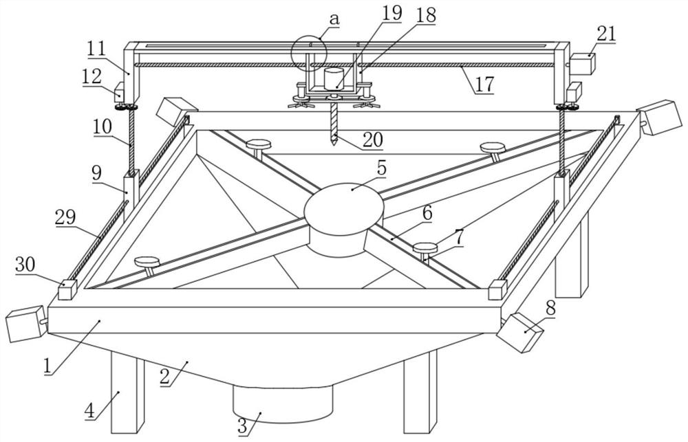
[0027] see attached drawings, refer to Figure 1-6 , a hole-making device for aircraft components, comprising a support frame 1, a collection bucket 2 is installed on the lower side wall of the support frame 1, a discharge pipe 3 is installed at the bottom end of the collection bucket 2, and the bottom of the collection bucket 2 is installed with four stand 4. The whole device is supported by the stand 4 .

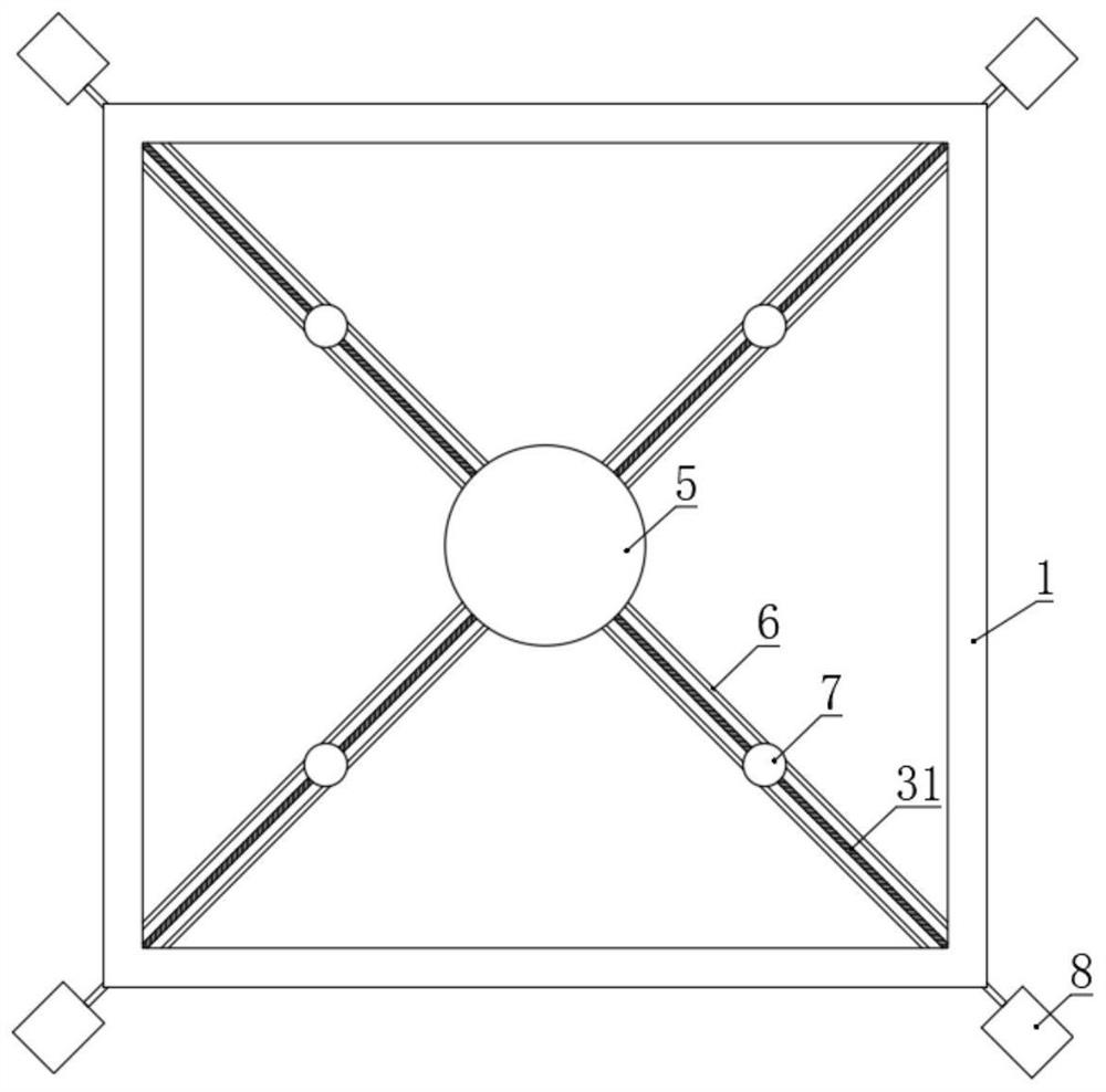
[0028] Four guide rails 6 are installed on the inner diagonal of the support frame 1, and one end of the four guide rails 6 close to the center of the support frame 1 is fixed with the placing table 5 together. The fourth threaded rod 31, the fourth threaded rod 31 is threadedly installed with the positioning pin 7, the four corners of the outer side of the support frame 1 are installed with the first motor 8, and the end of the fourth threaded rod 31 away from the placing table 5 is respectively connected with the first motor 8. The drive end of the motor 8 is installed...


PUM


Abstract

A drilling device comprises a supporting frame, a drilling mechanism and a movement mechanism, a positioning mechanism is arranged on the supporting frame, a collecting hopper and a discharging pipe are installed below the supporting frame, the drilling mechanism is fixed above the supporting frame through the movement mechanism, and the positioning mechanism is arranged on the supporting frame. The movement mechanism comprises a transverse movement mechanism, longitudinal movement mechanisms and vertical movement mechanisms, the drilling mechanism is connected to the transverse movement mechanism, the two ends of the transverse movement mechanism are connected to the upper ends of the two linked vertical movement mechanisms respectively, and the lower end of each vertical movement mechanism is connected to the two linked longitudinal movement mechanisms respectively. The two longitudinal movement mechanisms are horizontally connected to the two parallel borders of the supporting frame.

Description

technical field [0001] The invention relates to the technical field of machining, in particular to a hole-making device. Background technique [0002] There are many parts of the aircraft. For the most common parts of the aircraft, the most common operation is the hole making of the parts. After searching, the Chinese Patent No. CN 206241298 U discloses a hole making device for aircraft parts. The clamp, the beam is fixedly arranged directly above the work table through the bracket, the positioning plate is arranged directly under the beam through the first cylinder mechanism, and the punching device is fixedly arranged at the bottom end of the positioning plate; the left and right sides of the bottom end of the positioning plate are also provided with The second cylinder mechanism, a rubber pad is arranged between the second cylinder mechanism and the positioning plate, a number of vertically extending shock absorbing cavities are evenly arranged on the rubber pad, and a sh...

Claims


Application Information

Patent Timeline
Patent Type & Authority Applications(China)
IPC IPC(8): B23B41/00B23Q3/06B23Q1/25B23Q11/00
CPCB23B41/00B23Q3/06B23Q1/25B23Q11/005B23Q11/0067Y02P70/10
Inventor 解倩靓白云鹏李永鹏周宏遥张浩
Owner XI'AN AIRCRAFT INTERNATIONAL
Why Eureka
Try Eureka