Automatic strain gauge welding device

A welding device and strain gauge technology, which is applied in the direction of tin feeding device, auxiliary device, welding equipment, etc., can solve the problems of high temperature of soldering gun, scald people, low degree of automation, insufficient technical level, etc., and realize automatic movement of the card slot Effect

Active Publication Date: 2022-07-08
SHANDONG JIANZHU UNIV
View PDF6 Cites 0 Cited by
  • Summary
  • Abstract
  • Description
  • Claims
  • Application Information

AI Technical Summary

Problems solved by technology

[0002] In the process of strain gauge welding, traditional technology mostly uses manual welding, but manual welding has the problem of high solder gun temperature and burns people; and manual welding also has the problem that the welding quality does not meet the requirements of use due to insufficient technical level
In view of the problems existing in manual welding, some strain gauge welding devices have appeared, but the existing strain gauge welding devices are not highly automated and the operation process is complicated

Method used


Image

  • Automatic strain gauge welding device
  • Automatic strain gauge welding device
  • Automatic strain gauge welding device

Examples


Embodiment Construction

[0027] The technical solutions in the embodiments of the present invention will be clearly and completely described below with reference to the accompanying drawings in the embodiments of the present invention. Obviously, the described embodiments are only a part of the embodiments of the present invention, rather than all the embodiments. Based on the embodiments of the present invention, all other embodiments obtained by those of ordinary skill in the art without creative efforts shall fall within the protection scope of the present invention.

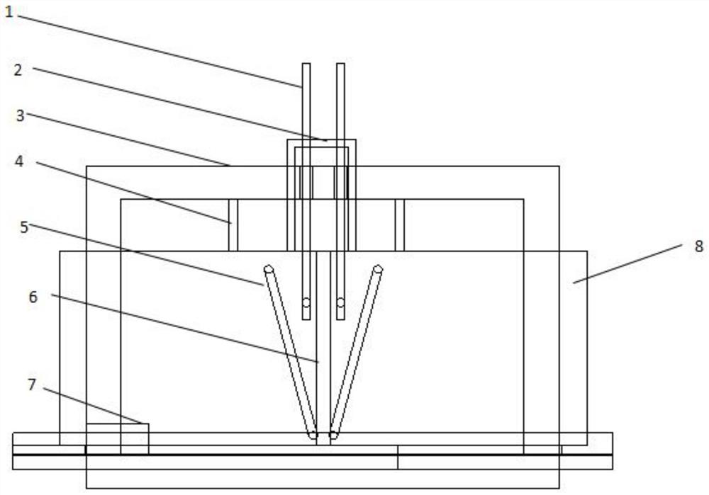
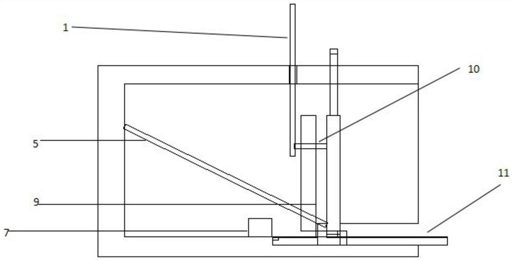
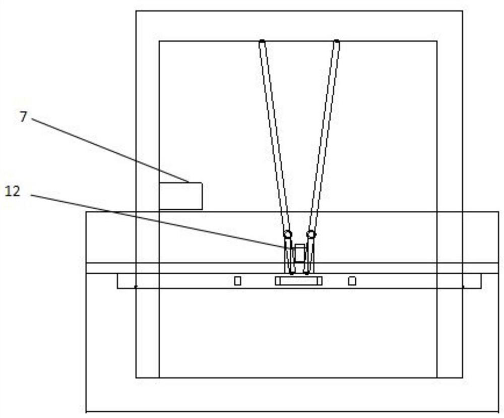
[0028] The purpose of the present invention is to provide an automatic strain gauge welding device, so as to solve the problems existing in the above-mentioned prior art, greatly save manpower, realize automatic welding, and improve welding quality.

[0029] In order to make the above objects, features and advantages of the present invention more clearly understood, the present invention will be described in further detail below with ...


PUM


Abstract

The invention discloses an automatic strain gauge welding device which comprises a lower pressing plate, a clamping groove plate, two soldering tin guns and two soldering tin wire guide pipes which are arranged in a shell, soldering tin wires penetrate through the soldering tin wire guide pipes and then make contact with metal bars of the soldering tin guns from soldering tin wire inlets to be melted, and the soldering tin wires flow into the clamping groove plate where terminals and strain gauges are placed through diversion trenches; a gear of the motor drives the clamping groove plate to automatically move, and the lower pressing plate can automatically ascend and descend at a fixed position. A welding port and a terminal welding point are accurately aligned by pushing and pulling the clamping groove plate; after the positioning buckles at the end parts of the lower pressing plate are inserted into the positioning holes, the positions of the clamping groove plates can be fixed; a strain gauge and a terminal are placed in the strain gauge area and the terminal area respectively. According to the automatic strain gauge welding device, after a tin wire automatically descends and makes contact with a tin soldering gun, liquid tin is formed, enters the flow guide groove and is shaped through the shaping hole, and a terminal and a strain gauge are reliably connected; and the functions of automatic movement of the clamping groove, automatic lifting of the lower pressing plate and accurate positioning of the terminal and the strain gauge can also be realized.

Description

technical field [0001] The invention relates to the technical field of strain gauge welding, in particular to an automatic strain gauge welding device. Background technique [0002] In the process of strain gage welding, traditional techniques mostly use manual welding, but manual welding has the problem that the temperature of the solder gun is too high and scalding people; and manual welding also has the problem that the welding quality does not meet the requirements for use due to insufficient technical level. In view of the problems existing in manual welding, some strain gage welding devices have appeared, but the existing strain gage welding devices are not highly automated, and the operation process is complicated. SUMMARY OF THE INVENTION [0003] The purpose of the present invention is to provide an automatic strain gauge welding device, so as to solve the problems existing in the above-mentioned prior art, greatly save manpower, realize automatic welding, and imp...

Claims


Application Information

Patent Timeline
Patent Type & Authority Applications(China)
IPC IPC(8): B23K3/06B23K3/08
CPCB23K3/063B23K3/08Y02P70/10
Inventor 王雨晗王磊玉
Owner SHANDONG JIANZHU UNIV
Why Eureka
Try Eureka