
Transfer manipulator for manufacturing optical glass

A technology of optical glass and manipulators, applied in the direction of program control manipulators, manipulators, manufacturing tools, etc., can solve problems such as low transfer efficiency and glass damage, and achieve the effect of avoiding damage and shattering

Active Publication Date: 2022-07-08
深圳传能科技有限公司
View PDF5 Cites 2 Cited by
  • Summary
  • Abstract
  • Description
  • Claims
  • Application Information

AI Technical Summary

Problems solved by technology

[0004] The purpose of the present invention is to solve the problem that the manual transfer efficiency of the optical glass is low and the glass is easily damaged due to collision with foreign objects in the process of transfer and transfer.

Method used


Image

  • Transfer manipulator for manufacturing optical glass
  • Transfer manipulator for manufacturing optical glass
  • Transfer manipulator for manufacturing optical glass

Examples


Embodiment 1

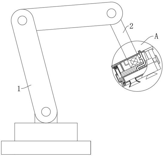
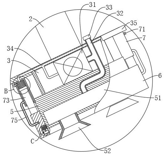
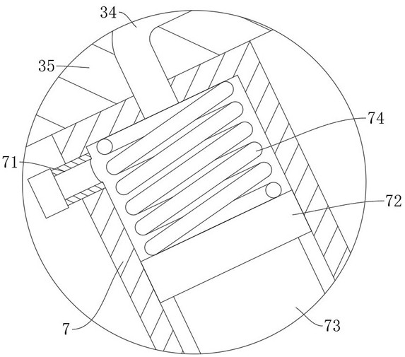
[0033] refer to Figure 1-Figure 8 , a transfer manipulator for manufacturing optical glass, comprising a manipulator 1 and a connecting rod 2 installed on the manipulator 1, and also comprising: a negative pressure cylinder 3 fixedly connected to the connecting rod 2, and the bottom of the negative pressure cylinder 3 is fixedly connected There is a bottom plate 5, the bottom of the bottom plate 5 is fixedly connected with a suction cup 52; the protection frame 6 is slidably connected on the bottom plate 5, the negative pressure cylinder 3 is fixedly connected with connecting blocks 35 on both sides, and the connecting block 35 is fixedly connected with a piston cylinder 7, the piston cylinder 7 is slidably connected with an ejector rod 73, and one end of the ejector rod 73 away from the piston cylinder 7 is fixedly connected to the protection frame 6; the negative pressure component is arranged in the negative pressure cylinder 3 to extract the air in the suction cup 52; it i...

Embodiment 2

[0036] refer to Figure 1-Figure 3 , Figure 5-Figure 6, a transfer manipulator for manufacturing optical glass, comprising a manipulator 1 and a connecting rod 2 installed on the manipulator 1, and also comprising: a negative pressure cylinder 3 fixedly connected to the connecting rod 2, and the bottom of the negative pressure cylinder 3 is fixedly connected There is a bottom plate 5, the bottom of the bottom plate 5 is fixedly connected with a suction cup 52; the protection frame 6 is slidably connected on the bottom plate 5, the negative pressure cylinder 3 is fixedly connected with connecting blocks 35 on both sides, and the connecting block 35 is fixedly connected with a piston cylinder 7, the piston cylinder 7 is slidably connected with an ejector rod 73, and one end of the ejector rod 73 away from the piston cylinder 7 is fixedly connected to the protection frame 6; the negative pressure component is arranged in the negative pressure cylinder 3 to extract the air in the...


PUM


Abstract

The invention discloses a transferring manipulator for optical glass manufacturing, and belongs to the technical field of transferring for optical glass manufacturing. A transfer manipulator for manufacturing optical glass comprises a mechanical arm and a connecting rod mounted on the mechanical arm, and further comprises a negative pressure cylinder fixedly connected to the connecting rod, and a bottom plate fixedly connected to the bottom of the negative pressure cylinder; the protection frame is connected to the bottom plate in a sliding manner; the air pump continuously works and is matched with the pressure regulating valve, so that a stable negative pressure value is generated in the cavity and the bottom plate so as to sufficiently and stably adsorb the optical glass in contact with the suction cup, and the protection frame is driven by air exhausted by the air pump to slide downwards so as to protect the peripheral edge of the optical glass; and meanwhile, a sliding rod connected to the protection frame in a sliding mode is driven to move below the optical glass in a reciprocating mode, dust at the bottom of the optical glass is fully removed in cooperation with sprayed air and a brush, manual dust removal is not needed, and the transferring efficiency in the optical glass manufacturing process is improved.

Description

technical field [0001] The invention relates to the technical field of transfer and loading for optical glass manufacturing, in particular to a transferring and loading manipulator for optical glass manufacturing. Background technique [0002] Optical glass is an amorphous optical medium material that transmits light. It can be used to make various optical components such as prisms, lenses, and filters. After the light passes through, it can change the propagation direction, phase and intensity. Optical glass is a photoelectric technology. The basic and important part of the industry, in the optical glass manufacturing process, it needs to be moved to a designated location and other operations. [0003] In the existing optical glass manufacturing process, when it is transferred and loaded, it is mostly carried and transferred manually, and the efficiency of manual transfer is relatively low, and it is easy to collide with foreign objects during the transfer and transfer proc...

Claims


Application Information

Patent Timeline
Patent Type & Authority Applications(China)
IPC IPC(8): B25J9/04B25J15/06B25J19/00B08B1/00B08B5/02
CPCB25J9/04B25J15/0616B08B5/02B25J19/00B08B1/12B08B1/30Y02P40/57
Inventor 肖瑞燕
Owner 深圳传能科技有限公司
Learn More