A meat stick filling machine
A filling machine and meat stick technology, applied in packaging and other directions, can solve the problems of automatic and orderly packaging of raw materials and low filling efficiency of meat sticks, so as to improve efficiency and automation, order and efficiency , Improve the effect of installation convenience
- Summary
- Abstract
- Description
- Claims
- Application Information
AI Technical Summary
Problems solved by technology
Method used
Image
Examples
Embodiment 1
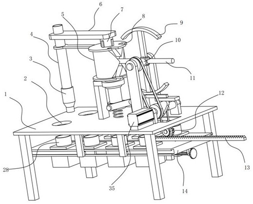
[0031] see Figure 1-7 , a meat stick filling machine, including a frame 1, the frame 1 is provided with two vertical holes 2, the bottom of the frame 1 is installed with a feeding slide 14, and several pairs of filling containers 28 are fixed on the feeding slide 14. and the carrying blocks 27 corresponding to the filling containers 28 one-to-one, the filling containers 28 are mounted on the carrying blocks 27 through the positioning assembly, each pair of filling containers 28 corresponds to two vertical holes 2 respectively, and are rotatably installed on the frame 1 There is a steering cylinder 5, a rotating column 7 is installed through the steering cylinder 5, and a rotating plate 6 is fixed on the rotating column 7;
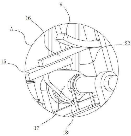
[0032] A vertically arranged filling conveying pipe 4 is fixed on the rotating plate 6, a filling head 3 is installed at the lower end of the filling conveying pipe 4, a motor 35 is installed on the frame 1, and the output shaft of the motor 35 is driven a...
Embodiment 2
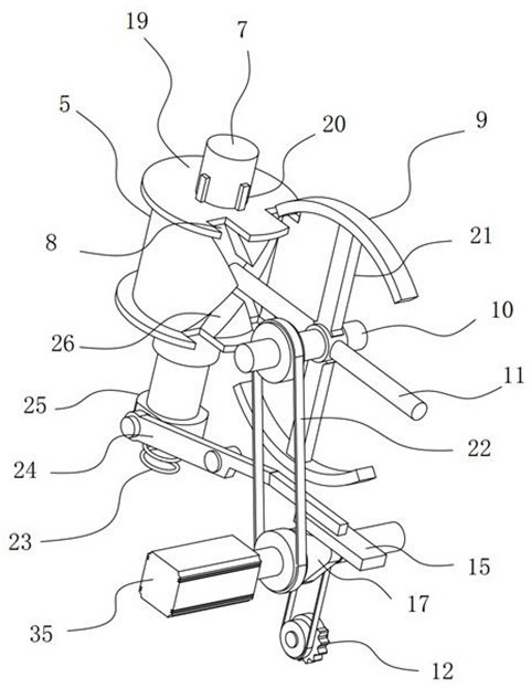
[0041] see Figure 1-7 On the basis of Embodiment 1, in addition, a baffle plate 19 is fixed on the top of the steering cylinder 5, two stop grooves 8 are opened on the baffle plate 19, a connecting rod 21 is fixed on the driven shaft 10, and the end of the connecting rod 21 is A stop arc plate 9 adapted to the stop groove 8 is installed.
[0042]In the process of starting the motor 35, it not only drives the cam 17 to rotate, but also drives the driven shaft 10 to rotate through the pulley mechanism II22. The driven shaft 10 drives the driving rod 11 to rotate, and the driving rod 11 is on the X-shaped guide groove 26. Sliding, the steering cylinder 5 is driven to deflect, and the two driving rods 11 are respectively slid once with the X-shaped guide groove 26, so that the steering cylinder 5 is deflected once and then reset, and the steering cylinder 5 drives the rotating column 7 through the clip 20 to deflect once and then reset , the filling head 3 is deflected once and ...
PUM
 Abstract
Description
Claims
Application Information
 - R&D
- Intellectual Property
- Life Sciences
- Materials
- Tech Scout
- Unparalleled Data Quality
- Higher Quality Content
- 60% Fewer Hallucinations
Browse by: Latest US Patents, China's latest patents, Technical Efficacy Thesaurus, Application Domain, Technology Topic, Popular Technical Reports.
© 2025 PatSnap. All rights reserved.Legal|Privacy policy|Modern Slavery Act Transparency Statement|Sitemap|About US| Contact US: help@patsnap.com


