Dirt cleaning and descaling device for fuel steam generator

A technology for decontamination, descaling and fuel steam, which is used in boiler cleaning devices, nuclear power generation, and greenhouse gas reduction. convenient effects

Inactive Publication Date: 2022-07-08
安徽安燃节能环保设备有限公司
View PDF0 Cites 0 Cited by
  • Summary
  • Abstract
  • Description
  • Claims
  • Application Information

AI Technical Summary

Problems solved by technology

[0003] The purpose of the present invention is to solve the problems of poor security and inconvenient replacement of wearing parts in the prior art, and propose a dirt and scale removal device for fuel steam generators

Method used


Image

  • Dirt cleaning and descaling device for fuel steam generator
  • Dirt cleaning and descaling device for fuel steam generator
  • Dirt cleaning and descaling device for fuel steam generator

Examples


Embodiment 1

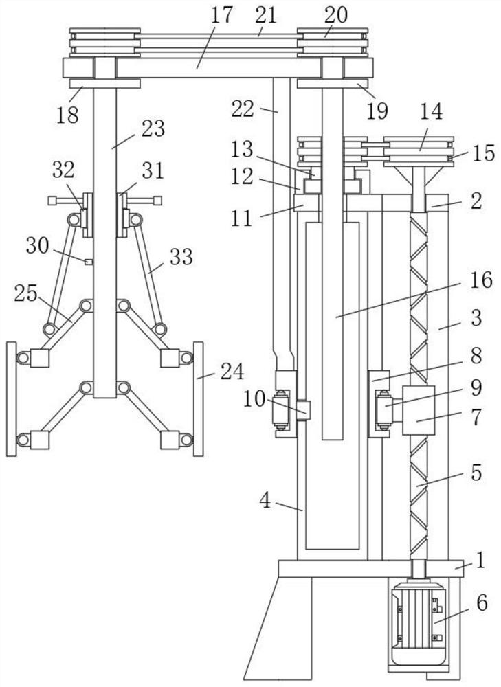
[0025] refer to Figure 1-4 , a decontamination and descaling device for a fuel steam generator, comprising a base 1, a top plate 2 and a dome table 11 fixed to each other are arranged vertically above the base 1, and between the bottom of the top plate 2 and the dome table 11 and the base 1 A column 3 and a rail vertical cylinder 4 are respectively fixed, a reciprocating screw 5 is rotatably installed between the top plate 2 and the base 1, a DC motor 6 is fixedly installed on one side of the base 1 by bolts, and the output shaft of the DC motor 6 is connected to the reciprocating screw. One end of 5 is drivingly connected, a rotating seat 12 is installed on the top side of the dome table 11, a rotating member 13 is rotatably installed in the rotating seat 12, and the rotating member 13 and the outer side of one end of the reciprocating screw , a transmission belt 15 is installed between the two pulleys 14, the rotating member 13 is provided with a polygonal vertical through ...

Embodiment 2

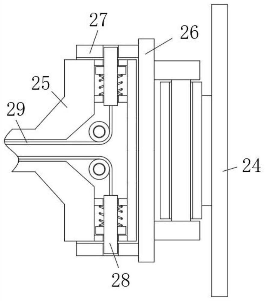
[0028] like Figure 1-4As shown, this embodiment is basically the same as Embodiment 1. Preferably, the outer side of the shaft body of the central shaft tube 23 is provided with a threaded groove and a threaded barrel 31 is threadedly sleeved. There is a collar 32, the bottom and the top of the scraper 24 are both hinged with a sizing umbrella shaft 25, and the other end of the sizing umbrella shaft 25 is hinged with the central axis tube 23, and the two central axis tubes 23 are arranged in parallel, A rotating connecting shaft 33 is rotatably installed between the middle part of the upper sizing umbrella shaft 25 and the vertical side of the collar 32 .

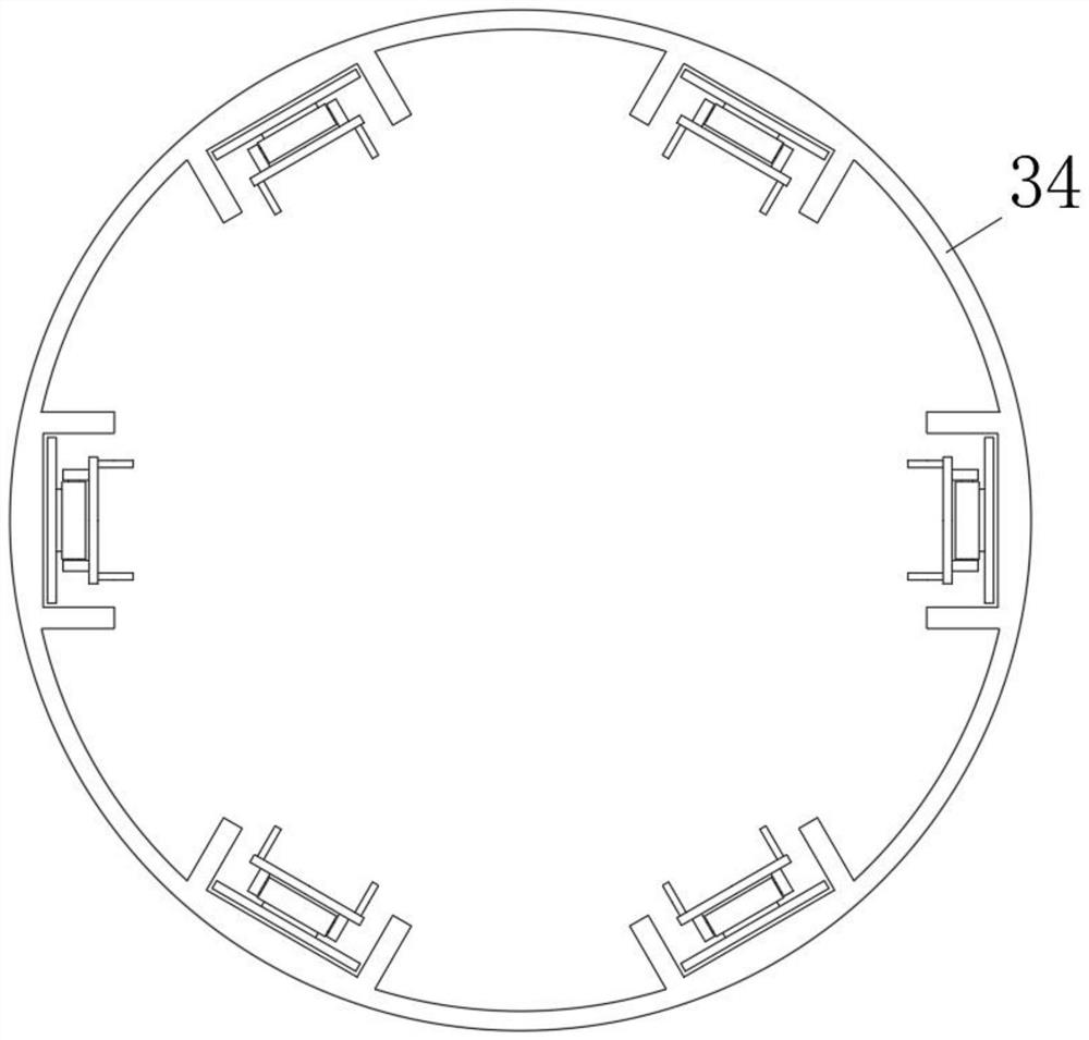
[0029] In this embodiment, when the inner wall is descaled for parts with different inner diameters, the threaded barrel 31 is manually screwed, the threaded barrel 31 moves in the vertical direction when the central axis tube 23 rotates, and the collar 32 moves relative to the threaded barrel 31 Rotating, the collar 32 m...

Embodiment 3

[0031] like Figure 1-4 As shown, this embodiment is basically the same as Embodiment 1. Preferably, one end of the sizing umbrella shaft 25 is sleeved with a card seat 27, one end of the card seat 27 is fixedly connected with an installation vertical plate 26, and the scraper 24 is pivoted and hinged On the side where the riser 26 is installed.

[0032] In this embodiment, the installation of the scraper 24 is realized through the cooperation between the card seat 27 and the elastic bayonet 28 .


PUM


Abstract

The decontamination and descaling device for the fuel oil steam generator comprises a base, a top plate and a round top table which are fixed to each other are arranged on the vertical upper portion of the base, a stand column and a rail vertical cylinder are fixed between the bottom of the top plate and the base and between the bottom of the round top table and the base respectively, and a reciprocating lead screw is rotationally installed between the top plate and the base; a direct-current motor is fixedly installed on one side of the base through a bolt, an output shaft of the direct-current motor is in transmission connection with one end of a reciprocating lead screw, a rotating seat is installed on the top side of the circular truncated cone, a rotating piece is rotationally installed in the rotating seat, and first belt wheels are coaxially and fixedly connected to the outer side of one end of the rotating piece and the outer side of one end of the reciprocating lead screw. The use of a large number of servo motors or air cylinders is avoided, so that the safety of equipment is greatly improved, the structure is simple and ingenious, the linkage performance is high, quick-wear parts are convenient to replace, operation is convenient and fast, and the use requirements of people in production and life are met.

Description

technical field [0001] The invention relates to the technical field of maintenance equipment for fuel steam generator parts, in particular to a decontamination and descaling device for fuel steam generators. Background technique [0002] In modern industry, industrial production powered by fuel steam is very common. The technology is mature and the cost is low. The fuel steam generator is the core component of the entire power supply. In the process of long-term use, the fuel generator is regularly Descaling is very necessary, and it is also a necessary means to ensure the energy conversion rate, while the existing fuel steam generator needs to use a large number of DC motors when descaleing a series of parts such as some cylindrical pipes and generator vessels. , which is more dangerous in the oil and gas environment, and the scale removal equipment uses an independent servo cylinder for vertical movement, horizontal equipment transfer, and the rotation and orbit of the scr...

Claims


Application Information

Patent Timeline
Patent Type & Authority Applications(China)
IPC IPC(8): F22B37/54
CPCF22B37/54Y02E30/30
Inventor 郑秋生郑家春刘艳
Owner 安徽安燃节能环保设备有限公司
Why Eureka
Try Eureka