
Rotor axis track purification method

A technology of axis trajectory and purification method, which is applied in the direction of impedance network, instrument, character and pattern recognition, etc., can solve the problems of statistical bias, large amount of calculation, unfavorable automatic realization of purification algorithm, etc., and achieve the effect of improving the suppression ability

Pending Publication Date: 2022-07-08
苏州德姆斯信息技术有限公司
View PDF0 Cites 0 Cited by
  • Summary
  • Abstract
  • Description
  • Claims
  • Application Information

AI Technical Summary

Problems solved by technology

However, purification methods such as wavelet transform, wavelet packet transform, and harmonic window need to predict the fault characteristic frequency band of the rotor in advance, and then reconstruct the signal in the time domain according to the frequency band range of the useful component in the signal. Different frequency band range selection and basis function The choice of α directly affects the purification effect, which is not conducive to the automatic realization of the purification algorithm; the EMD-based axis trajectory purification method is constrained by the problems of EMD algorithm itself, such as modal aliasing and endpoint effects, and is purely digitally driven, with a large amount of calculation; The purification method based on mathematical morphological filtering results in large or small output due to the opening and closing operation, and there is a phenomenon of statistical bias, and the output of the filter will have a certain deviation compared with the actual one.

Method used


Image

  • Rotor axis track purification method
  • Rotor axis track purification method
  • Rotor axis track purification method

Examples


Embodiment Construction

[0050]In order to make those skilled in the art better understand the solutions of the present invention, the technical solutions in the embodiments of the present invention will be clearly and completely described below with reference to the accompanying drawings in the embodiments of the present invention. Obviously, the described embodiments are only Embodiments are part of the present invention, but not all embodiments. Based on the embodiments of the present invention, all other embodiments obtained by persons of ordinary skill in the art without creative efforts shall fall within the protection scope of the present invention.

[0051] It should be noted that the terms "first", "second" and the like in the description and claims of the present invention and the above drawings are used to distinguish similar objects, and are not necessarily used to describe a specific sequence or sequence. It is to be understood that the data so used may be interchanged under appropriate c...


PUM


Abstract

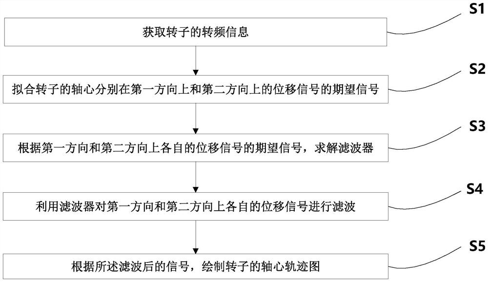
The invention discloses a rotor axis track purification method. The method comprises the following steps: S1, acquiring rotation frequency information of a rotor; s2, setting a first direction and a second direction, and fitting expected signals of displacement signals of the axis of the rotor in the first direction and the second direction according to the rotation frequency information of the rotor; s3, according to the expected signals of the respective displacement signals in the first direction and the second direction, solving to obtain a filter; s4, inputting respective displacement signals in the first direction and the second direction into the filter solved in the step S3 to obtain filtered signals; and S5, according to the filtered signal, drawing an axis trajectory diagram of the rotor. According to the method, the characteristics of the displacement signals are effectively utilized, the adaptive filter with a feedback structure is adopted for digital filtering, the noise suppression capability can be greatly improved, and a clear and real rotor axis track diagram is obtained.

Description

technical field [0001] The invention relates to the fields of mechanical health monitoring and fault diagnosis, in particular to a method for purifying a rotor axis track. Background technique [0002] The shaft of the equipment for rotating motion must have bearing parts, called bearings, and the rotor is a rotating body supported by bearings. [0003] The rotor's axis trajectory is ideally a point, but with the mechanical wear caused by the operation of the equipment, the rotor's axis trajectory deviates from the ideal point. [0004] When the equipment is in normal working state, the main frequency component of the rotor displacement signal is one frequency. When the rotor has a misalignment fault, the axis trajectory of the rotor will become a crescent or banana shape, and if the fault is aggravated, it will become a "8" shape. When the oil film whirling occurs in the rotor, the shape corresponding to the axis track is mostly an inner "8" shape. [0005] Therefore, th...

Claims


Application Information

Patent Timeline
IPC IPC(8): G06K9/00H03H21/00
CPCH03H21/0043H03H2021/0056G06F2218/04
Inventor 邓刚张玉斌
Owner 苏州德姆斯信息技术有限公司
Learn More