Precise and comfortable injection system for botulinum toxin and use method thereof

An injection system, botulinum toxin technology, applied in the directions of syringes, hypodermic injection devices, infusion sets, etc., can solve the problem of too much or too little injection, unable to fix the syringe, etc., and achieve the effect of avoiding needle deviation

Pending Publication Date: 2022-07-12
罗忠祥
View PDF1 Cites 0 Cited by
  • Summary
  • Abstract
  • Description
  • Claims
  • Application Information

AI Technical Summary

Problems solved by technology

[0005] The purpose of the present invention is to solve the problem that the syringe cannot be fixed in the prior art, and the injection volume is too much or too little, and a compact botulinum toxin accurate and comfortable injection system and its use method are proposed

Method used


Image

  • Precise and comfortable injection system for botulinum toxin and use method thereof
  • Precise and comfortable injection system for botulinum toxin and use method thereof
  • Precise and comfortable injection system for botulinum toxin and use method thereof

Examples


Embodiment 1

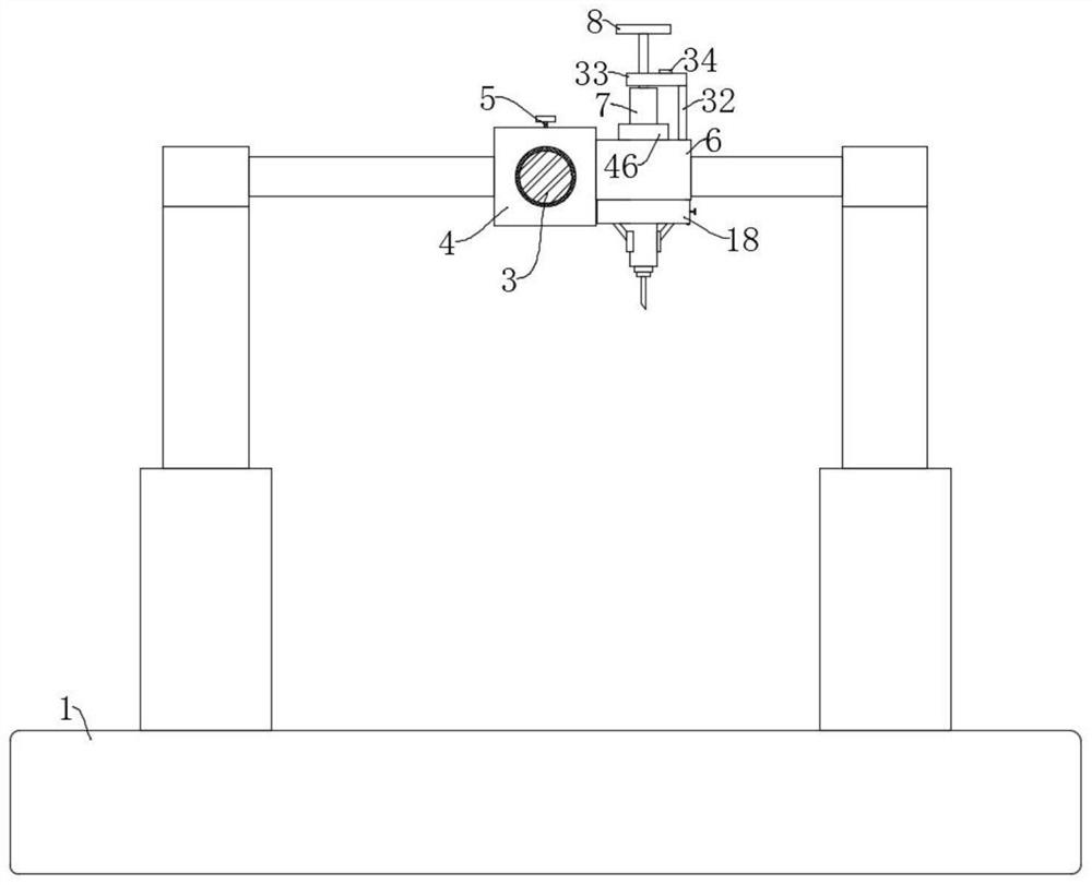
[0042] refer to Figure 1-8 , Botox precise and comfortable injection system, including base 1 and slide bar 3 connected above base 1, the outer wall of slide bar 3 is sleeved with a rectangular block 4, the top thread of the rectangular block 4 runs through a bolt 5, and the top of the bolt 5 is fixed A round handle 9 is connected, one side of the rectangular block 4 is connected with a fixing block 6 and a clamping plate 18 by bolts, and the bottom side of the clamping plate 18 is connected with an infrared laser transmitter 36 by bolts, and the infrared laser transmitter 36 emits Infrared rays, the position to be injected can be quickly found through infrared rays, and the top of the clamping plate 18 and the bottom of the fixing block 6 are fixedly connected by bolts, the fixing block 6 and the clamping plate 18 are provided with the same syringe 7, and the outer wall of the syringe 7 is fixedly sleeved with The fixing ring 46 is fixed, and the bottom of the fixing ring 46...

Embodiment 2

[0048] refer to Figure 1-9 , Botox precise and comfortable injection system, including base 1 and slide bar 3 connected above base 1, the outer wall of slide bar 3 is sleeved with a rectangular block 4, the top thread of the rectangular block 4 runs through a bolt 5, and the top of the bolt 5 is fixed A round handle 9 is connected, one side of the rectangular block 4 is connected with a fixing block 6 and a clamping plate 18 by bolts, and the bottom side of the clamping plate 18 is connected with an infrared laser transmitter 36 by bolts, and the infrared laser transmitter 36 emits Infrared rays, the position to be injected can be quickly found through infrared rays, and the top of the clamping plate 18 and the bottom of the fixing block 6 are fixedly connected by bolts, the fixing block 6 and the clamping plate 18 are provided with the same syringe 7, and the outer wall of the syringe 7 is fixedly sleeved with The fixing ring 46 is fixed, and the bottom of the fixing ring 46...


PUM


Abstract

According to the scheme, the accurate and comfortable injection system comprises a base and a sliding rod connected to the upper portion of the base, the outer wall of the sliding rod is sleeved with a rectangular block, a bolt penetrates through the top of the rectangular block in a threaded mode, and a round handle is fixedly connected to the top end of the bolt; a fixing block and a clamping plate are fixedly connected to one side of the rectangular block, the top of the clamping plate is fixedly connected with the bottom of the fixing block, and the same injector is arranged in the fixing block and the clamping plate. The first rotating disc and the second rotating disc can be driven to rotate by rotating the rotating shaft and the rotating handle so that the clamping blocks and the arc-shaped plates can clamp an injector, the clamping blocks and the arc-shaped plates are arranged in a staggered mode so that the injector can be clamped more stably, the injector is prevented from deviating, movement of the U-shaped plate can be controlled while the injector is clamped, and therefore the injection efficiency is improved. The method is used for accurately controlling the injection amount of the creotoxin and avoiding the situation that the injection amount of the creotoxin does not conform to the predicted amount.

Description

technical field [0001] The invention relates to the technical field of medical devices, in particular to a botulinum toxin precise and comfortable injection system and a method for using the same. Background technique [0002] Botulinum toxin injection is one of the important methods for the treatment of muscle spasm at present, and the botulinum toxin injection technology guided by myoelectric stimulation is widely used in clinical practice. Due to the high cost of botulinum toxin and the inability to repeat injections in a short period of time, precise injection of botulinum toxin is crucial for patients. [0003] The utility model with the publication number of CN213220059U discloses a botulinum toxin auxiliary injection device, which comprises a base, the four corners of the top surface of the base are fixedly connected with hydraulic rods, and the top surfaces of the four groups of the hydraulic rods are fixedly connected There are mounting blocks, a lead screw is rota...

Claims


Application Information

Patent Timeline
Patent Type & Authority Applications(China)
IPC IPC(8): A61M5/178A61M5/31A61M5/315A61M5/42
CPCA61M5/178A61M5/31A61M5/31548A61M5/427
Inventor 罗忠祥
Owner 罗忠祥
Why Eureka
Try Eureka