
Weld joint positioning device and welding equipment for aluminum alloy automatic butt joint trolley

A positioning device and automatic docking technology, which is applied in welding equipment, arc welding equipment, metal processing equipment, etc., can solve the problems of low efficiency of flat butt welding of aluminum alloy materials, reduce the influence of human factors and labor intensity, and save labor costs , good flexibility

Pending Publication Date: 2022-07-12
JIANGNAN SHIPYARD GRP CO LTD
View PDF18 Cites 0 Cited by
  • Summary
  • Abstract
  • Description
  • Claims
  • Application Information

AI Technical Summary

Problems solved by technology

[0005] In view of the above shortcomings of the prior art, the purpose of the present invention is to provide a welding seam positioning device and welding equipment for aluminum alloy automatic butt joint trolley to solve the technical problem of low efficiency of flat butt welding of aluminum alloy materials

Method used


Image

  • Weld joint positioning device and welding equipment for aluminum alloy automatic butt joint trolley
  • Weld joint positioning device and welding equipment for aluminum alloy automatic butt joint trolley
  • Weld joint positioning device and welding equipment for aluminum alloy automatic butt joint trolley

Examples


Embodiment 1

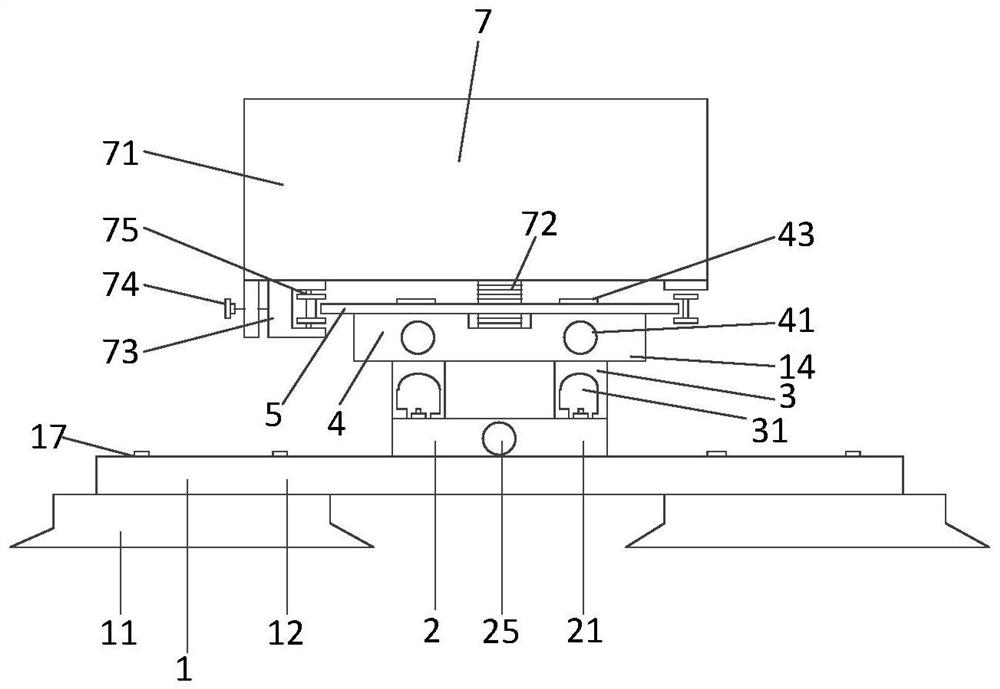
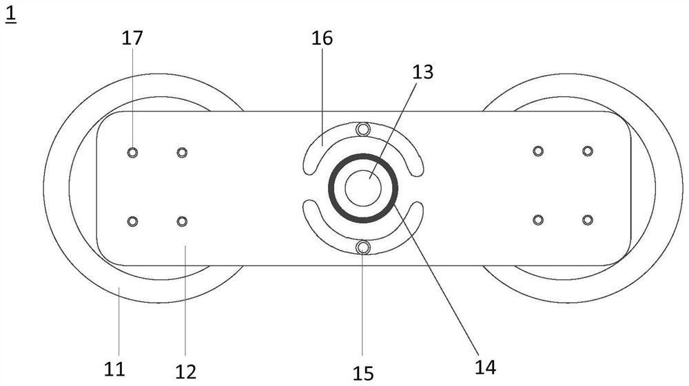
[0087] This embodiment provides a welding seam positioning device for an aluminum alloy automatic docking trolley. The welding seam positioning device includes a walking track and at least one suction cup assembly for fixing the walking track, wherein: the walking track has a first surface and a second surface arranged oppositely. Two surfaces, the first surface of the walking track is used for welding the trolley to form a connection. The suction cup assembly is fixedly arranged on the second surface of the traveling track, so as to adsorb the traveling track to the predetermined welding seam position.

[0088] Therefore, the welding seam positioning device described in this embodiment can fix the walking track at the predetermined welding seam position of the non-magnetic material to be welded through the suction cup assembly, which facilitates the precise positioning of the welding seam positioning device and realizes stable quality and high efficiency. Automate the welding...

Embodiment 2

[0099] This embodiment also provides a welding device, which includes the welding seam positioning device described in the above embodiment, and a welding trolley 7 disposed above the welding seam positioning device. The welding trolley 7 cooperates with the traveling track to move along the first surface of the traveling track 5 .

[0100] Specifically, refer to figure 1 , the welding trolley 7 includes a trolley body 71 and a gear 72 , the gear 72 is fixedly arranged under the trolley body 71 , and the gear 72 meshes with the tooth slot of the walking track 5 . In addition, a welding arm (not shown in the figure) is provided on the carriage body 71 .

[0101] In an alternative embodiment, refer to figure 1 and figure 2 , the welding trolley 7 also includes a movable slider 73, an adjusting screw 74 and a clamping wheel. The movable slider 73 is fixed under the trolley body 71 and can reciprocate along the extending direction X perpendicular to the running track; the adj...


PUM


Abstract

The invention discloses a welding seam positioning device and welding equipment for an aluminum alloy automatic butt welding trolley, the welding seam positioning device comprises a walking track and at least one suction cup assembly, the walking track is provided with a first surface and a second surface which are oppositely arranged, and the first surface of the walking track is used for being connected with the welding trolley; the at least one suction cup assembly is fixedly arranged on the second surface of the walking track so that the walking track can be sucked to the preset welding seam position. The walking track can be fixed to the preset welding seam position of the non-magnetic material to be welded through the suction cup assembly, accurate positioning of butt joint welding seams of non-magnetic materials such as aluminum alloy is achieved, and the automatic welding process stable in quality and high in efficiency is guaranteed.

Description

technical field [0001] The invention relates to the technical field of shipbuilding welding, in particular to a welding seam positioning device and welding equipment for an aluminum alloy automatic butt-jointing trolley. Background technique [0002] The all-aluminum structure boat has the characteristics of light weight, fast and flexible, and is widely used in special ships such as high-speed tourist boats and yachts, and can obtain excellent lightweight effect and high sailing speed. Due to its excellent seawater corrosion resistance, high specific strength and ease of workability, 5-series aluminum alloys have become the main materials for lightweight aluminum alloy ships. [0003] The construction of aluminum alloy ships is mainly based on welding processing. Due to the non-magnetic characteristics of aluminum alloys, it is difficult to directly use conventional steel welding trolleys that use magnetic tracks to achieve weld positioning. Therefore, in the welding proce...

Claims


Application Information

Patent Timeline
Patent Type & Authority Applications(China)
IPC IPC(8): B23K9/12B23K9/32
CPCB23K9/12B23K9/32
Inventor 邓胜杰王涛应银生李红卫张彬李根汤文
Owner JIANGNAN SHIPYARD GRP CO LTD
Learn More