Cutting device for rectifier bridge support mold machining

A technology of mold processing and cutting device, applied in metal processing equipment, manufacturing tools, welding equipment, etc., can solve the problem of high production cost of cutting device

Inactive Publication Date: 2022-07-12
江苏众联祥博新能源科技有限公司
View PDF0 Cites 4 Cited by
  • Summary
  • Abstract
  • Description
  • Claims
  • Application Information

AI Technical Summary

Problems solved by technology

[0004] When using a laser to cut the rectifier bridge bracket mold, the traditional cutting method requires multiple motors to control the position and angle of the laser cutting device, and additional equipment is required to clamp and limit the rectifier bridge bracket mold. The production cost of the cutting device for the processing of the rectifier bridge bracket mold is relatively high, and the clamping and cutting integration of the rectifier bridge bracket mold cannot be realized. Therefore, we propose a cutting device for the processing of the rectifier bridge bracket mold to solve the above problems

Method used


Image

  • Cutting device for rectifier bridge support mold machining
  • Cutting device for rectifier bridge support mold machining
  • Cutting device for rectifier bridge support mold machining

Examples


Embodiment

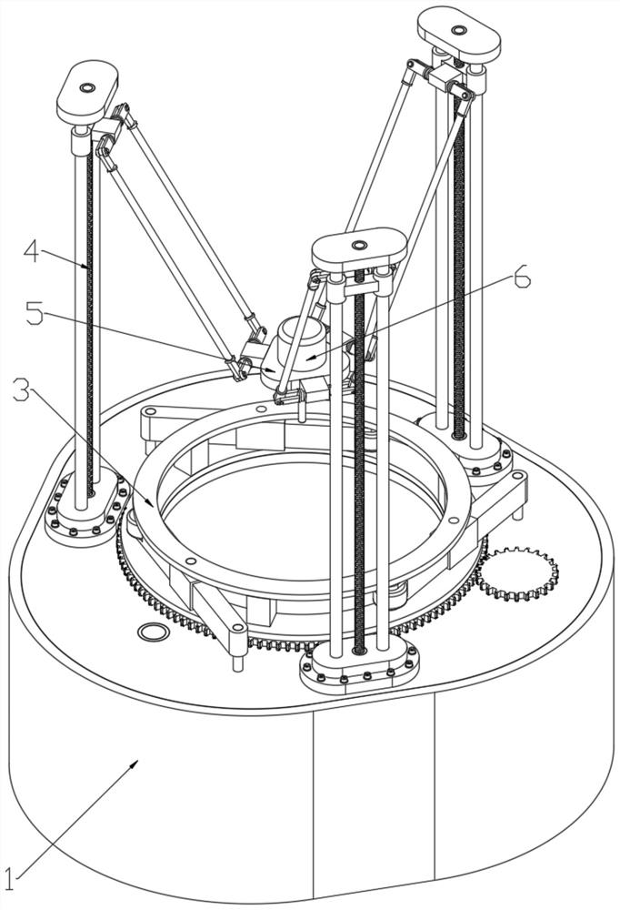
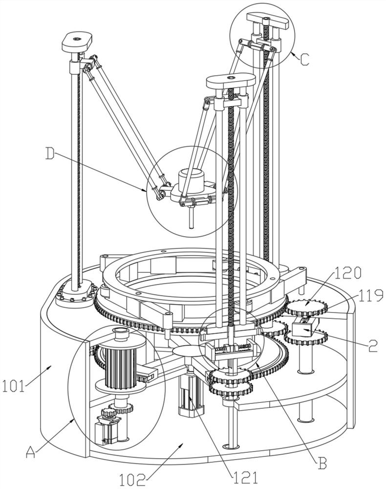
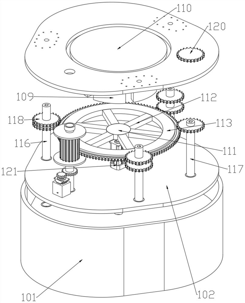
[0032] Example: as Figure 1-10As shown, the present invention provides a cutting device for machining a rectifier bridge bracket mold, including a drive mechanism 1, and the drive mechanism 1 includes three support plates 102 distributed up and down, and two support plates located below A second transmission shaft 117 and three annularly distributed first transmission shafts 116 are arranged on the 102 through the bearing rotation. The first transmission shaft 116 and the second transmission shaft 117 are both provided with a limit mechanism 2, and the uppermost The center of the top of the support plate 102 is provided with a clamping mechanism 3, the outer ring of the clamping mechanism 3 is annularly distributed with three adjustment mechanisms 4, and the three adjustment mechanisms 4 are fixedly installed on the top of the uppermost support plate 102, A base 5 is installed between the three adjusting mechanisms 4 , and a laser cutting device 6 is installed at the center o...


PUM


Abstract

The invention discloses a cutting device for rectifier bridge support mold machining, and particularly relates to the technical field of rectifier mold machining, the cutting device comprises a driving mechanism, four limiting mechanisms are arranged in the driving mechanism, a clamping mechanism is arranged at the center of the top end of the driving mechanism, and three adjusting mechanisms are annularly distributed on the outer ring of the clamping mechanism; the three adjusting mechanisms are all fixedly installed at the top end of the driving mechanism, the base is installed among the three adjusting mechanisms, the laser cutting device is installed in the center of the base, the driving mechanism is used for driving the clamping mechanism or the adjusting mechanisms to work, and the clamping mechanism is used for clamping and limiting a rectifier bridge support mold. The adjusting mechanism is used for adjusting the distance between the laser cutting device and the rectifier bridge support mold and adjusting the cutting angle of the laser cutting device, so that multi-angle cutting can be conducted on the rectifier bridge support mold.

Description

technical field [0001] The invention relates to the technical field of rectifier mould processing, in particular to a cutting device used for processing a rectifier bridge bracket mould. Background technique [0002] The rectifier bridge generally has a large enough inductive load, so the rectifier bridge does not have current interruptions. In general rectifier bridge applications, a smoothing reactor is often connected to its load end, so its load can be regarded as a constant current source. Multiple groups of three-phase rectifier bridges are connected to each other, so that the harmonics generated by the rectifier bridge circuit cancel each other out. [0003] Laser cutting refers to the use of high power density laser beam to irradiate the material to be cut, so that the material is quickly heated to the vaporization temperature and evaporated to form holes. cutting. [0004] When using laser to cut the rectifier bridge bracket mold, the traditional cutting method r...

Claims


Application Information

Patent Timeline
Patent Type & Authority Applications(China)
IPC IPC(8): B23K26/08B23K26/38B23K26/70
CPCB23K26/38B23K26/0884B23K26/702Y02P70/10
Inventor 赵娜龚雪丹唐海龙胡心彬
Owner 江苏众联祥博新能源科技有限公司
Why Eureka
Try Eureka