
Turning center

A turning center and central axis technology, applied in the direction of manufacturing tools, metal processing machinery parts, measuring/indicating equipment, etc., can solve the problems of damage to processed workpieces, reduce turning processing efficiency, and difficult processing knives, so as to facilitate replacement and improve processing effect of effect

Pending Publication Date: 2022-07-12
常州汎亚液压机器有限公司
View PDF0 Cites 0 Cited by
  • Summary
  • Abstract
  • Description
  • Claims
  • Application Information

AI Technical Summary

Problems solved by technology

[0003] Traditional turning centers do not have a corresponding tool wear monitoring system, and most of them are judged manually, resulting in a large error range of monitoring results and a large amount of manpower. If they are not replaced in time, they will easily damage the workpiece and greatly reduce the turning efficiency. Secondly, Due to the need to process different positions of the workpiece, it is difficult for the existing machining knives to achieve a variety of angle changes, and it is impossible to achieve the processing effect on different positions of the workpiece

Method used

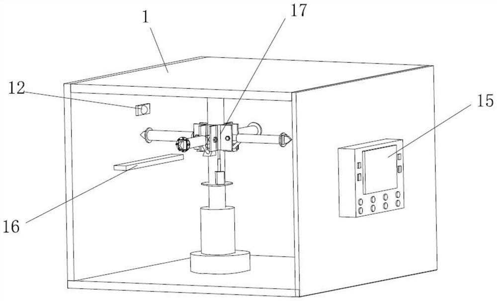
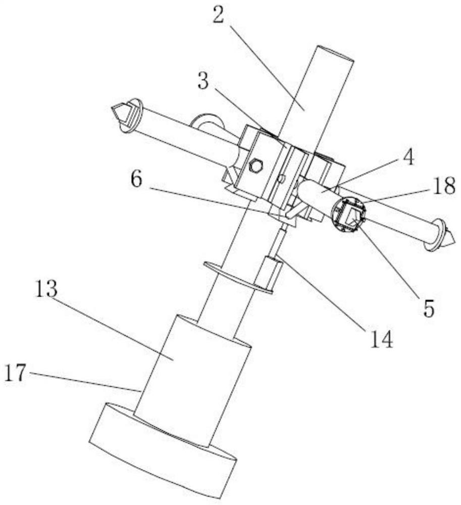
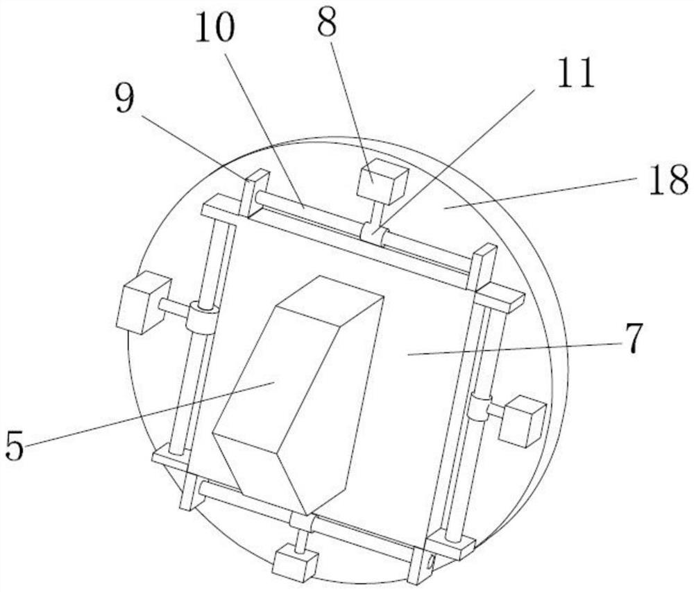

Image

  • Turning center
  • Turning center
  • Turning center

Examples


Embodiment Construction

[0020] The technical solutions of the present invention will be clearly and completely described below with reference to the accompanying drawings. Obviously, the described embodiments are a part of the embodiments of the present invention, but not all of the embodiments. Based on the embodiments of the present invention, all other embodiments obtained by those of ordinary skill in the art without creative efforts shall fall within the protection scope of the present invention.

[0021] In the description of the present invention, it should be noted that when the terms "center", "upper", "lower", "left", "right", "vertical", "horizontal", "inner", "outer" appear. ”, etc., the indicated orientation or positional relationship is based on the orientation or positional relationship shown in the accompanying drawings, only for the convenience of describing the present invention and simplifying the description, rather than indicating or implying that the indicated device or element m...


PUM


Abstract

The invention discloses a turning center, and relates to the technical field of numerical control turning centers, the turning center comprises a shell, the turning center is arranged on the inner side of the shell, the turning center comprises a center shaft, a connecting sleeve, a connecting shaft, a machining cutter, a first air cylinder and an adjusting mechanism, a machining station is arranged on the inner side of the shell, and the center shaft is arranged on the machining station; the upper end of the center shaft is rotatably connected with the inner wall of the upper side of the shell, the outer edge of the center shaft is sleeved with a connecting sleeve, a plurality of connecting shafts are arranged on the outer edge of the connecting sleeve, an adjusting mechanism is arranged at the end, away from the connecting sleeve, of each connecting shaft, a machining cutter is arranged on each adjusting mechanism, and a plurality of first air cylinders are arranged on the outer edge of the connecting sleeve. Each first air cylinder is connected with the corresponding connecting shaft. According to the device, the position of the machining cutter in the vertical direction can be adjusted, the position of the machining cutter can be controlled to be adjusted in the horizontal direction and the vertical direction, the machining cutter can be controlled to conduct arc-shaped displacement, and multi-directional adjustment and machining angle control over the machining cutter can be conveniently achieved.

Description

technical field [0001] The invention relates to the technical field of numerical control turning centers, in particular to a turning center. Background technique [0002] The turning center takes the lathe as the basic body, and further adds the functions of power milling, drilling, boring, and sub-spindle on the basis of it, so that the processes that require the second and third processing of the lathe can be completed on the turning center at one time. [0003] Traditional turning centers do not have a corresponding tool wear monitoring system, and most of them are judged manually, resulting in a large error range of monitoring results and a lot of manpower. If not replaced in time, it is easy to damage the workpiece, which greatly reduces the turning efficiency. Due to the need to process different positions of the workpiece, it is difficult for the existing machining tool to achieve various angle changes, and cannot achieve the processing effect on different positions o...

Claims


Application Information

Patent Timeline
IPC IPC(8): B23Q1/25B23Q17/09B23Q17/24
CPCB23Q1/25B23Q17/0957B23Q17/2457Y02W30/40
Inventor 张坤
Owner 常州汎亚液压机器有限公司
Learn More