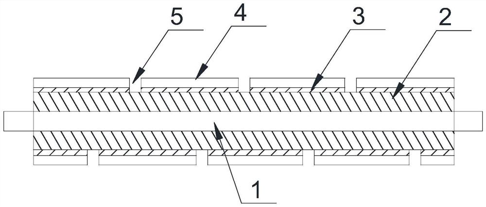
Grinding roller for cleaning liquid crystal panel and preparation method of grinding roller
A liquid crystal panel and grinding roller technology, which is applied in the direction of grinding tools, grinding/polishing equipment, grinding devices, etc., can solve the problems of scrap cleaning yield, panel degradation, and large scratch risk, so as to avoid the risk of scratch , reduce production costs, ensure the effect of grinding yield and stability
- Summary
- Abstract
- Description
- Claims
- Application Information
AI Technical Summary
Problems solved by technology
Method used
Image
Examples
preparation example Construction
[0055] The present invention provides a method for preparing a grinding roller for cleaning a liquid crystal panel, based on the grinding roller for cleaning a liquid crystal panel according to any of the above embodiments, comprising:
[0056] The abrasive layer 4 is spirally arranged on the support layer, the abrasive layer 4 is extended along the axial direction of the support layer, and the abrasive layer 4 has a gap in the axial direction of the support layer to form a chip flute.
[0057] In this way, through the grooves and chip removal grooves 5 of the grinding layer 4 of the functional layer, during the grinding and cleaning process of the grinding roller to the workpiece, the grinding dust can be stored in time, and the secondary damage to the grinding workpiece caused by the hard grinding dust can be avoided. , to avoid the risk of scratching; in addition, the helical structure of the chip flute 5 can remove excess wear debris in time, which can ensure continuous gri...
Embodiment 1
[0073] Example 1: Select acrylic resin and polyurethane for compounding in a ratio of 1:2, and mix and disperse uniformly with aluminum hydroxide abrasive by high-speed stirring to obtain a coating slurry, and the particle size of the abrasive is 9 μm; the uniformly dispersed mixed slurry The material is coated on the buffer base material to obtain the abrasive layer 4; the foamed PP wrap is attached to the outer ring surface of the support bearing 1 to prepare an elastic shaft roller; the double-sided foam film with a hardness of 24 degrees Shore hardness and The grinding layer 4 is compounded, and the corresponding width of 20mm is cut out according to the size of the grinding roller, and then the axial angle (the included angle with the axis of the support bearing 1) is 45 degrees and spirally adheres to the elastic shaft roller to ensure chip removal. The width of groove 5 is 5mm; the edge of the grinding roller is trimmed, and the edges and corners of the grinding roller a...
Embodiment 2
[0075] Example 2: Select acrylic resin and polyurethane for compounding according to the ratio of 1:2, and mix and disperse evenly with aluminum hydroxide abrasive by high-speed stirring to obtain a coating slurry, and the particle size of the abrasive is 9 μm; the uniformly dispersed mixed slurry The material is coated on the buffer base material to obtain the abrasive layer 4; the foamed PP wrap is attached to the outer ring surface of the support bearing 1 to prepare an elastic shaft roller; the double-sided foam film with a hardness of 24 degrees Shore hardness and The grinding layer 4 is compounded, and the corresponding width of 20mm is cut according to the size of the grinding roller, and then the axial angle (the included angle with the axis of the support bearing 1) is 10 degrees and spirally adheres to the elastic shaft roller to ensure chip removal. The width of groove 5 is 5mm; the edge of the grinding roller is trimmed, and the edges and corners of the grinding rol...
PUM
| Property | Measurement | Unit |
|---|---|---|
| width | aaaaa | aaaaa |
| Shore hardness | aaaaa | aaaaa |
| Shore hardness | aaaaa | aaaaa |
Abstract
Description
Claims
Application Information
 - R&D
- Intellectual Property
- Life Sciences
- Materials
- Tech Scout
- Unparalleled Data Quality
- Higher Quality Content
- 60% Fewer Hallucinations
Browse by: Latest US Patents, China's latest patents, Technical Efficacy Thesaurus, Application Domain, Technology Topic, Popular Technical Reports.
© 2025 PatSnap. All rights reserved.Legal|Privacy policy|Modern Slavery Act Transparency Statement|Sitemap|About US| Contact US: help@patsnap.com


