
Unmanned helicopter tail transmission structure

An unmanned helicopter and tail drive technology, which is applied in the direction of motor vehicles, aircraft power transmission, and aircraft power devices, etc., can solve the problems of tail drive shaft vibration, tail drive shaft deformation, easy misalignment, etc., and achieve easy installation and small deformation , the effect of reducing vibration

Pending Publication Date: 2022-07-12
北京航景创新科技有限公司
View PDF9 Cites 0 Cited by
  • Summary
  • Abstract
  • Description
  • Claims
  • Application Information

AI Technical Summary

Problems solved by technology

[0002] UAV helicopters are developing rapidly, and are more and more widely used in surveying and mapping, rescue and fire fighting. The transmission of the tail of the UAV is very important, and the transmission mode of the tail of the UAV is also constantly developing; For unmanned helicopters, the tail transmission line of unmanned helicopters is long, and the tail transmission shaft is prone to large deformation during the transmission process, and the tail transmission shaft will produce severe vibration. At the same time, during the vibration process of the tail transmission shaft, the tail transmission shaft The inner ring of the bearing is particularly prone to misalignment, which will affect the transmission stability of the tail drive shaft

Method used


Image

  • Unmanned helicopter tail transmission structure
  • Unmanned helicopter tail transmission structure
  • Unmanned helicopter tail transmission structure

Examples


Embodiment Construction

[0031] The present invention will be described in detail below with reference to the accompanying drawings and embodiments.

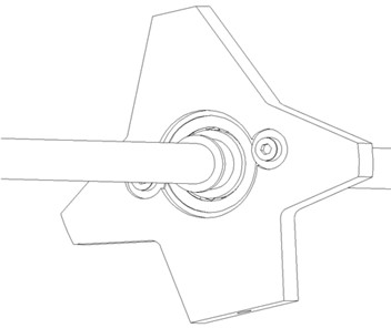
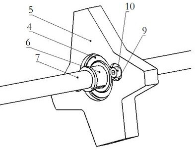
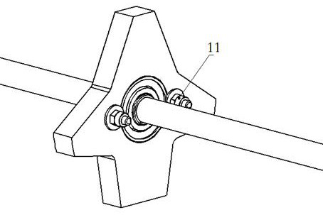
[0032] This embodiment provides a tail drive structure of an unmanned helicopter, see appendix figure 1 , including: coupling rear flange 1, coupling front flange 2, coupling 3, deep groove ball bearing 4, tail shaft support 5, tail shaft positioning sleeve 6, tail shaft 7, tail shaft The transmission shaft connecting piece 8 and the support cylinder of the tail transmission shaft;

[0033] One end of the tail shaft 7 is connected with the power unit of the unmanned helicopter through the coupling 3, and the other end of the tail shaft 7 is connected with the tail rotor of the unmanned helicopter through the tail shaft connector 8;

[0034] Among them, see appendix figure 2 , the coupling 3 adopts a hexagonal plum blossom coupling, and the two ends of the coupling 3 are respectively connected with the power unit and the tail shaft 7 through the rear ...


PUM


Abstract

The invention discloses a tail transmission structure of an unmanned helicopter, belongs to the technical field of transmission devices of unmanned helicopters, and solves the problems that a tail transmission line of the unmanned helicopter is long, a tail transmission shaft is easy to deform greatly in the transmission process and can vibrate violently, and meanwhile, the tail transmission shaft is not easy to deform in the vibration process. The tail transmission structure comprises a deep groove ball bearing, a tail transmission shaft support, a tail transmission shaft positioning sleeve, a tail transmission shaft and a tail transmission shaft supporting cylinder. The tail transmission shaft is coaxially installed in the tail transmission shaft supporting cylinder through a tail transmission shaft support. The more than two tail transmission shaft supports are uniformly distributed along the length direction of the tail transmission shaft; and each tail transmission shaft support is coaxially sleeved on the tail transmission shaft through a deep groove ball bearing and a tail transmission shaft positioning sleeve. Deformation of the tail transmission shaft in the long-distance transmission process can be reduced, and vibration of the tail transmission shaft is greatly reduced.

Description

technical field [0001] The invention belongs to the technical field of transmission devices of unmanned helicopters, and in particular relates to a tail transmission structure of unmanned helicopters. Background technique [0002] UAV helicopters are developing rapidly, and they are more and more widely used in surveying and mapping, rescue and fire fighting. The transmission of the tail of the UAV is very important, and the transmission mode of the tail of the UAV is also constantly developing; but for large-scale helicopters For unmanned helicopters, the unmanned helicopter has a long tail transmission route, and the tail transmission shaft is prone to large deformation during the transmission process, and the tail transmission shaft will produce violent vibration. At the same time, during the vibration process of the tail transmission shaft, the tail transmission shaft The inner ring of the bearing is particularly prone to dislocation, which in turn affects the transmissi...

Claims


Application Information

Patent Timeline
IPC IPC(8): B64C27/12B64D35/00
CPCB64C27/12B64D35/00B64U10/10Y02T50/40
Inventor 吴双王伟杜聪魁陈心刚王龙马玲玲
Owner 北京航景创新科技有限公司
Learn More