Coke oven carbon reduction and coke prevention method and system
A coke oven and anti-coking technology, which is applied in the coking oven, coking oven heating, combustible gas heating coking oven, etc., can solve the problems of coking on the top of the furnace and difficult removal, so as to increase the production temperature, eliminate the turnaround time, and eliminate the environment Effects of Chemical Pollution
- Summary
- Abstract
- Description
- Claims
- Application Information
AI Technical Summary
Problems solved by technology
Method used
Image
Examples
Embodiment 1
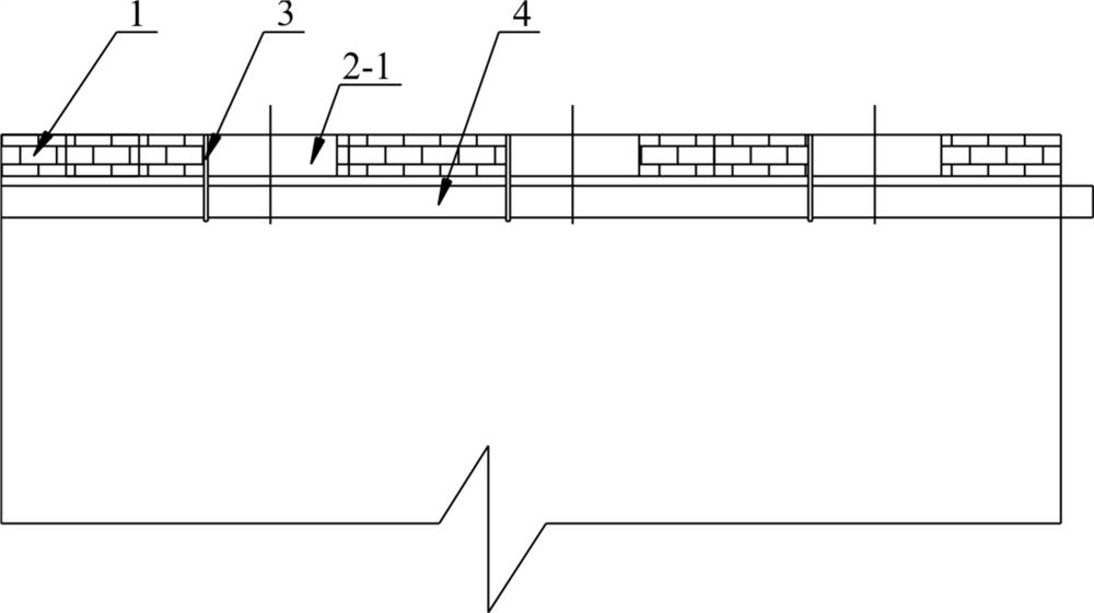
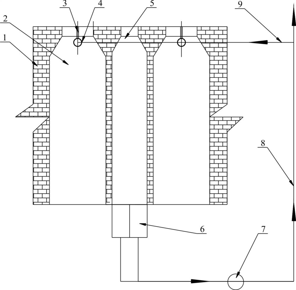
[0047] like Figure 1-2 The shown coke oven carbon reduction and anti-coke system includes a coking and carbonizing chamber 2 and a combustion chamber 5 arranged in the coke oven 1. The top of the coking and carbonizing chamber 2 is provided with an air intake pipe 4, and the top of the coking and carbonizing chamber 2 is provided with The coal feeding manhole 2-1, the air inlet pipe 4 runs through the carbonization chamber 2 of the coke oven 1, and the air inlet pipe 4 is hoisted on the top of the carbonization chamber 2 through the bracket 3 (the bracket 3 can be preferentially installed at the top of the carbonization chamber 2 when the existing coke oven 1 is improved. Near the riser pipe, if the new equipment is installed, the location can be selected according to needs), the air intake pipe 4 is provided with a number of air holes, the bottom of the combustion chamber 5 is provided with a regenerator 6, the regenerator 6 is connected to the flue chimney 8, and the flue is...
Embodiment 2
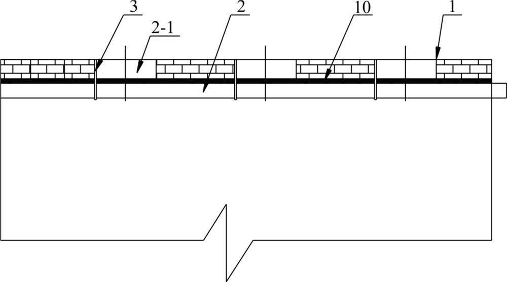
[0049] like Figure 3-4 As shown, in this embodiment, on the basis of Embodiment 1, a catalyst mesh 10 is arranged on the top of the intake pipe 4, and the catalyst mesh 10 is installed on the top of the carbonization chamber 2 through a grid-structured catalyst support 3, and the catalyst accelerates and promotes the carbonization chamber. 2 Reversible reaction at the top, and the action of the catalyst makes the chemical reaction to the desired goal occur.
Embodiment 3
[0051] like Figure 5-6 As shown, in this embodiment, on the basis of Embodiment 1, the outer periphery of the intake pipe 4 is covered with a catalyst mesh 10, which can be installed in a sleeved manner. The principle is the same as that of Embodiment 2.
PUM
 Abstract
Description
Claims
Application Information
 - R&D Engineer
- R&D Manager
- IP Professional
- Industry Leading Data Capabilities
- Powerful AI technology
- Patent DNA Extraction
Browse by: Latest US Patents, China's latest patents, Technical Efficacy Thesaurus, Application Domain, Technology Topic, Popular Technical Reports.
© 2024 PatSnap. All rights reserved.Legal|Privacy policy|Modern Slavery Act Transparency Statement|Sitemap|About US| Contact US: help@patsnap.com


