Device and method for controlling and measuring inclination of drilled hole of steel rope impact type drilling machine
A technology of a measuring device and a control method, which is applied in the directions of surveying, directional drilling, earth-moving drilling, etc., can solve the problems of time-consuming and laborious, hole wall damage, complicated detection process, etc., and achieves simple device structure, simple operation, simple and convenient control and Measuring the effect of work
- Summary
- Abstract
- Description
- Claims
- Application Information
AI Technical Summary
Problems solved by technology
Method used
Image
Examples
Embodiment 1
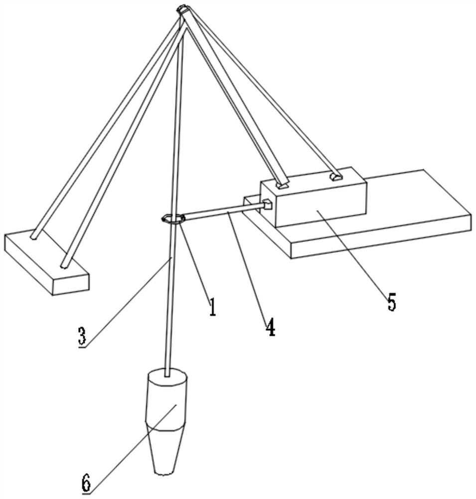
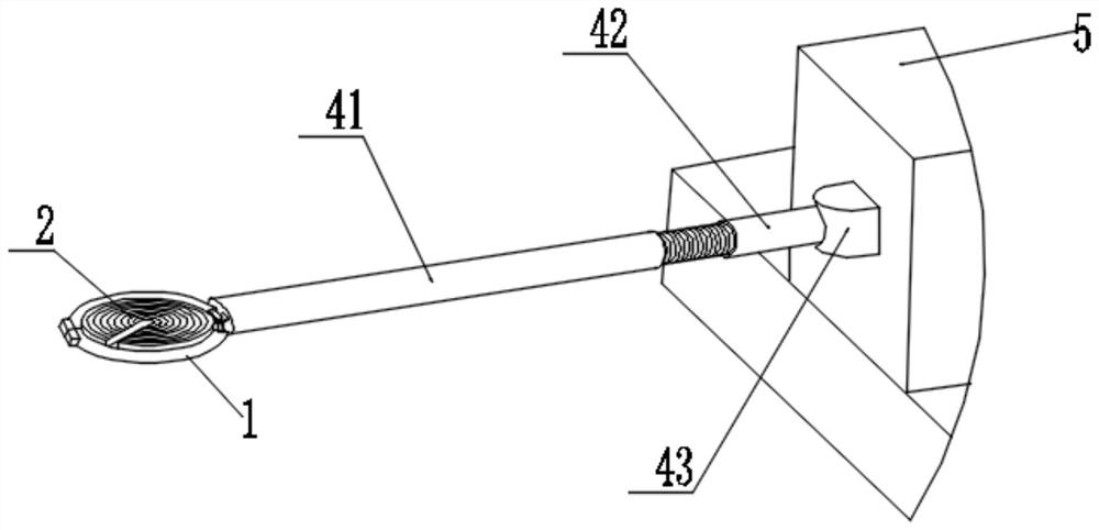
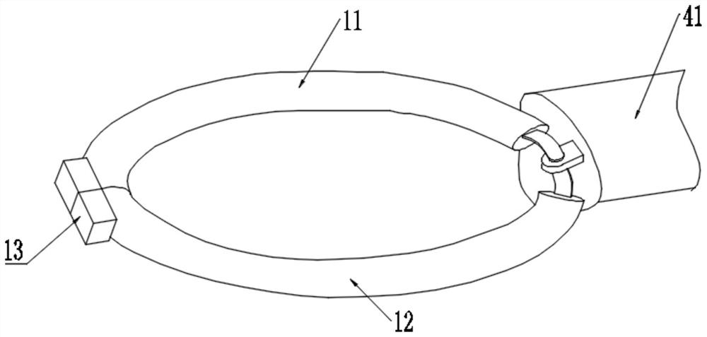
[0051] like Figure 1 to Figure 5 As shown in the figure, a device for controlling and measuring the drilling inclination of a steel rope impact drilling rig according to the present invention includes an inclination control ring 1 and a measuring disc 2. The annular section of the inclination control ring 1 is set horizontally, and the axis of the steel rope 3 is vertical. Straight through the center of the annular section of the inclination control ring 1, when the steel rope 3 contacts the inclination control ring 1, the inclination of the steel rope 3 is the maximum inclination required by the construction; 1. A limit control is formed for the inclination of the steel rope 3 to ensure that the inclination of the steel rope 3 is within the scope of the construction requirements, so as to ensure that the inclination of the drilling hole does not exceed the maximum inclination of the construction requirements, so as to ensure that the drilling construction does not affect the ...
Embodiment 2
[0063] This embodiment provides an inclination control method on the basis of Embodiment 1.
[0064] Using the inclination control method of the inclination control and measurement device, the inclination control method is as follows:
[0065] First, complete the setting of the steel wire hammer drill, at this time, the axes of the steel wire 3 and the hammer drill 6 are both vertically downward and collinear with the axis of the drill hole;
[0066] Then, the setting of the inclination control ring 1 is performed. At this time, the semi-circular ring a11 and the semi-circular ring b12 of the inclination control ring 1 are in the open state, and the central position of the inclination control ring 1 is adjusted through the threaded sleeve 42 and the connecting steel pipe 41 , to ensure that the axis of the steel rope 3 passes through the center of the inclination control ring 1;
[0067] Finally, the control of the inclination of the drilling rig is completed. When the axis o...
Embodiment 3
[0069] This embodiment provides an inclination measurement method on the basis of Embodiment 2
[0070] An inclination measurement method based on the inclination control method, the inclination measurement method is as follows:
[0071] When the inclination control ring 1 completes the control of the inclination, the measuring plate 2 is installed in the inclination control ring 1. At this time, the steel rope 3 is located in the measuring groove of the measuring plate 2, and the inclination of the steel rope 3 can be adjusted. Drive the measuring disc 2 to rotate in the inclination control ring 1, and at the same time the steel rope 3 can slide in the measuring groove;
[0072] Read the inclination offset distance d of the steel rope 3 at the inclination control ring 1 through the center distance mark 1 ;
[0073] Through the calculation of the vertical inclination ζ of the borehole, the deviation can be corrected in time according to the value of ζ.
[0074] like Image...
PUM
 Abstract
Description
Claims
Application Information
 - R&D
- Intellectual Property
- Life Sciences
- Materials
- Tech Scout
- Unparalleled Data Quality
- Higher Quality Content
- 60% Fewer Hallucinations
Browse by: Latest US Patents, China's latest patents, Technical Efficacy Thesaurus, Application Domain, Technology Topic, Popular Technical Reports.
© 2025 PatSnap. All rights reserved.Legal|Privacy policy|Modern Slavery Act Transparency Statement|Sitemap|About US| Contact US: help@patsnap.com


