Impurity collecting and processing device for hydroenergy power generation
A technology for processing devices and debris, applied in hydropower, engine components, machines/engines, etc., can solve problems such as low, debris is not easy to fall back into the water, collection efficiency of debris falling into the water, etc., to achieve the effect of accelerating efficiency
- Summary
- Abstract
- Description
- Claims
- Application Information
AI Technical Summary
Problems solved by technology
Method used
Image
Examples
specific Embodiment approach 1
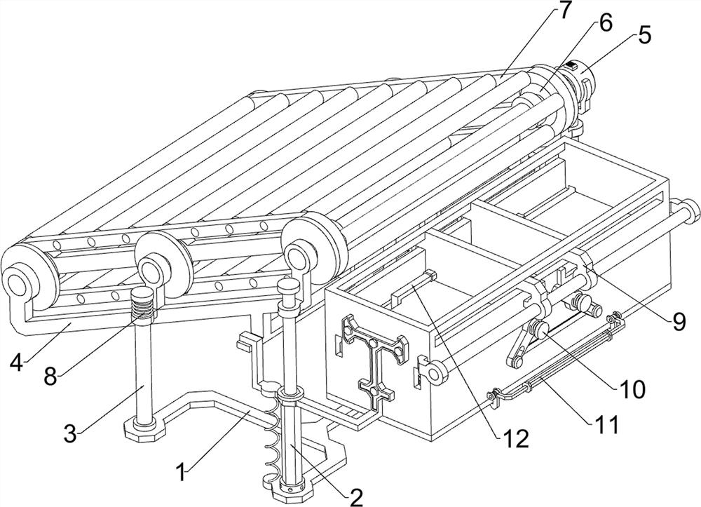
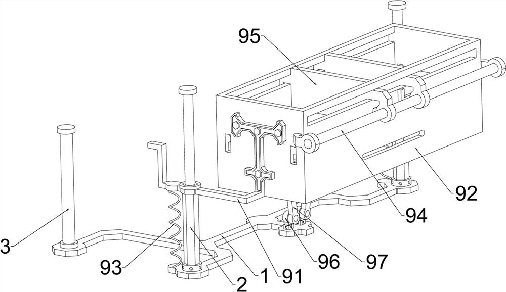
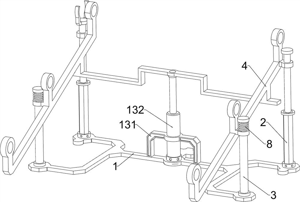
[0036] A debris collection and treatment device for hydropower generation, please see Figure 1-7 , including a base 1, a sleeve 2, a sliding rod 21, a first guide rod 3, a first fixed frame 4, a motor 5, a rotating wheel 6, a conveyor belt 7, a first spring 8, a collection mechanism 9 and a closing mechanism 10, the base The bottom of 1 is provided with anti-slip texture, which is convenient for the base 1 to be firmly prevented from being on the ground, so that the base 1 is not easy to slide. The right side of the top of the base 1 is connected with two bushings 2 by bolts, and the two bushings 2 are arranged symmetrically in the front and rear. , the tops of the two sleeves 2 are slidably connected with sliding rods 21, and the left side of the top of the base 1 is connected with two first guide rods 3 by welding. A first fixed frame 4 is connected between the sliding rod 21 on the side and the first guide rod 3, the first fixed frame 4 is slidably matched with the two fir...
specific Embodiment approach 2
[0040] On the basis of the specific embodiment 1, please check figure 1 , figure 2 , Figure 8 , Figure 9 and Figure 10 , and also includes a blanking mechanism 11, the blanking mechanism 11 includes a second fixed block 111, a filter screen 112, a rotating rod 113, a first rotating frame 114 and a second torsion spring 115, collecting the front and rear sides of the left wall of the frame 92 A second fixing block 111 is connected by welding, and a filter screen 112 is rotatably connected between the two second fixing blocks 111. The filter screen 112 is located at the bottom of the collection frame 92, and the front and rear sides of the right wall of the collection frame 92 are welded by welding. A rotating rod 113 is connected, and the rotating rods 113 are all located below the connecting rod 104 . A first rotating frame 114 is rotatably connected between the two rotating rods 113 . A second torsion spring 115 is connected between them, the two second torsion spring...
specific Embodiment approach 3
[0042] On the basis of the specific implementation mode 2, please check figure 1 and Figure 11 , and also includes a pulling mechanism 12, the pulling mechanism 12 includes a second connecting frame 121, a second scraper 122, and the sides of the two first scrapers 95 away from each other are connected with a second connecting frame by welding. 121. Both of the two second connecting frames 121 are slidably fitted with the collecting frame 92. The right end of the left second connecting frame 121 and the left end of the right second connecting frame 121 are connected with a second scraper 122 by welding. The second scraper 122 is located below the right second scraper 122 , and the two second scrapers 122 are both located above the filter screen 112 .
[0043] When the conveyor belt 7 moves downward again to collect the sundries in the water surface, the first connecting frame 91 will drive the collecting frame 92 to move downward. After the collecting frame 92 moves downward...
PUM
 Abstract
Description
Claims
Application Information
 - R&D
- Intellectual Property
- Life Sciences
- Materials
- Tech Scout
- Unparalleled Data Quality
- Higher Quality Content
- 60% Fewer Hallucinations
Browse by: Latest US Patents, China's latest patents, Technical Efficacy Thesaurus, Application Domain, Technology Topic, Popular Technical Reports.
© 2025 PatSnap. All rights reserved.Legal|Privacy policy|Modern Slavery Act Transparency Statement|Sitemap|About US| Contact US: help@patsnap.com


