Self-meshing coupling and using method thereof

A technology of couplings and semi-couplings, applied in the direction of couplings, rigid shaft couplings, mechanical equipment, etc., can solve the problems of increasing moment of inertia, cumbersome installation, cumbersome and time-consuming, etc., to ensure coaxiality Precision, reasonable structure design, simple and convenient installation

Active Publication Date: 2022-07-12
潍坊水发供水集团有限公司
View PDF4 Cites 0 Cited by
  • Summary
  • Abstract
  • Description
  • Claims
  • Application Information

AI Technical Summary

Problems solved by technology

The existing couplings are generally cumbersome to install. During installation, the coaxiality between the motor shaft and the working device must be ensured, and constant concentricity adjustments are required. This process is cumbersome, time-consuming, and inefficient; Moreover, in the actual operation process, since different components have different sizes, in the actual installation process, it is difficult to ensure the alignment accuracy of the coaxiality, which will cause the parts to jump, increase the moment of inertia, and shorten the service life of the coupling. The overall equipment will also be affected by this, with large vibration, high noise, and even safety accidents
In addition, due to the cumbersome installation of the existing couplings, for some emergency situations where quick installation is required, it may be too late to install, affecting production

Method used


Image

  • Self-meshing coupling and using method thereof
  • Self-meshing coupling and using method thereof
  • Self-meshing coupling and using method thereof

Examples


Embodiment 1

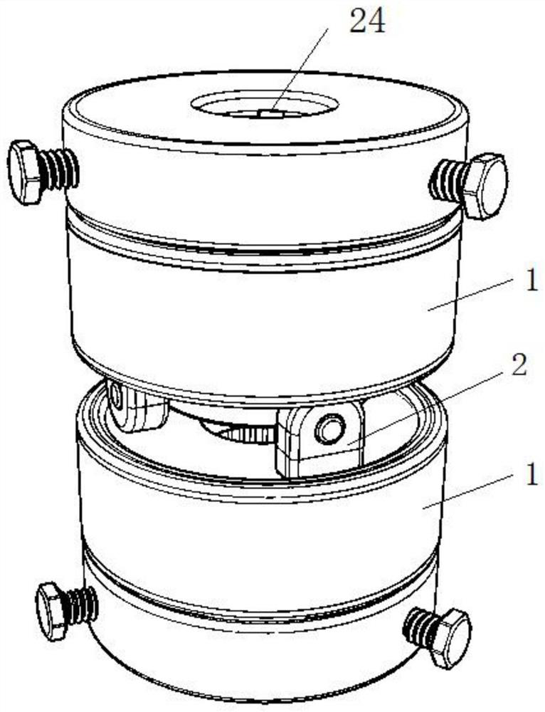
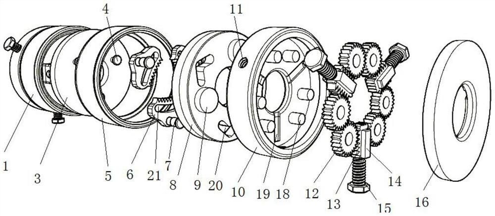
[0036] like Figure 1-7 As shown, the present embodiment proposes a self-engaging coupling, including two half-couplings 1, which are connected by a universal fork 2; The installation channel 24 of the rotating shaft 23; the half coupling 1 includes a snap shaft assembly and a positioning shaft assembly connected with the bite shaft assembly.

[0037] Elaborate above and below:

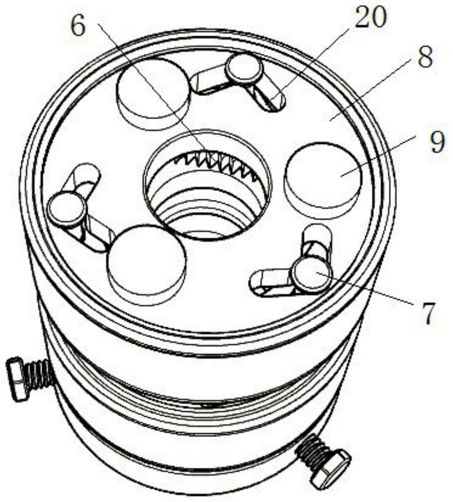
[0038] The bite shaft assembly includes a drive plate 3 connected with the universal fork 2, and the drive plate 3 is connected with a rotating shell 5; the drive plate 3 is connected with three evenly distributed lever shafts 4; the rotating shell 5 is provided with three arc teeth 6, The three cambered teeth 6 are evenly arranged in the circumferential direction, and the three cambered teeth 6 enclose an engagement cavity for engaging the rotating shaft 23 ; each cambered tooth 6 is provided with an arcuate groove 21 corresponding to the lever shaft 4 Each lever shaft 4 is movably placed in the co...

Embodiment 2

[0051] Reference attached Figure 8 , the self-engaging coupling proposed in this embodiment also includes a connecting shaft placed between the two half-couplings 1, and the two ends of the connecting shaft are respectively connected with the two half-couplings 1 through the universal fork 2 . In the present invention, a connecting shaft is also provided, and the connecting shaft is respectively connected with the two half-couplings 1 through the two universal fork heads 2, so that the difference of the compensation is larger, which is convenient for installation.

[0052] It can be seen from the above two embodiments that the cooperating use of the positioning shaft assembly and the bite shaft assembly in the present invention can not only ensure the coaxiality accuracy, but also quickly realize the quick connection between the coupling and the rotating shaft 23; the present invention It can be used in some emergency situations to achieve quick installation, reduce maintena...


PUM


Abstract

The invention provides a self-meshing coupling and a using method thereof.The self-meshing coupling comprises two half couplings connected through a universal fork head, and each half coupling comprises a meshing shaft assembly and a positioning shaft assembly; the biting shaft assembly comprises a transmission disc connected with the universal fork head, and the transmission disc is connected with a rotating shell. The transmission disc is connected with a lever shaft; cambered surface teeth are arranged in the rotary shell and are provided with arc-shaped grooves corresponding to the lever shafts; the cambered surface tooth is also connected with a swing shaft; the rotary shell is connected with a swing tooth sliding rail, a swing tooth groove corresponding to the swing shaft is formed in the swing tooth sliding rail, and the swing tooth groove is in a V shape. The positioning shaft assembly comprises a positioning shaft box body and a top cover which are connected with the swinging tooth sliding rail; six linkage gears are rotationally connected into the positioning shaft box body; every two linkage gears are meshed to form three meshed gear sets; a double-sided rack is meshed between any two adjacent meshing gear sets; and the side wall of the positioning shaft box body is connected with a top tooth screw. According to the invention, the coaxiality precision can be ensured, and quick connection can be realized.

Description

technical field [0001] The invention belongs to the technical field of shaft couplings, and particularly relates to a self-engaging shaft coupling and a using method thereof. Background technique [0002] In the existing large-scale electromechanical equipment, couplings are generally used to connect a plurality of transmission components between the motor and the working device for power transmission. The existing couplings are generally cumbersome to install. During installation, the coaxiality between the motor shaft and the working device must be guaranteed, and the concentricity adjustment needs to be continuously performed. This process is cumbersome and time-consuming, and the efficiency is low; And in the actual operation process, since different parts have different sizes, in the actual installation process, the alignment accuracy of the coaxiality is difficult to guarantee, which will cause the parts to jump and increase the moment of inertia, thereby shortening th...

Claims


Application Information

Patent Timeline
Patent Type & Authority Applications(China)
IPC IPC(8): F16D1/108
CPCF16D1/108
Inventor 张杰夏重庆张勇张明兴刘天奇
Owner 潍坊水发供水集团有限公司
Why Eureka
Try Eureka