Motor power line conduction testing device

A technology of continuity test and motor power supply, which is applied in the field of motor power line continuity test device, can solve the problems of increasing labor costs, increasing testing procedures, and prolonging working time, so as to achieve convenient and efficient operation, improve test efficiency, and reduce operation time. effect of difficulty

Pending Publication Date: 2022-07-12
达晟(上海)电子有限公司
View PDF0 Cites 0 Cited by
  • Summary
  • Abstract
  • Description
  • Claims
  • Application Information

AI Technical Summary

Problems solved by technology

[0004] However, the following problems were found in the traditional test fixture during the test operation: in the prepared power cord, some terminals were slightly inclined, and the inclined terminals could not be well connected with the corresponding test points during the test process. contacts, and therefore are often falsely detected as non-conductive
At this time, although the pressure can be increased to make it contact with the test point, it is easy to cause other terminals to be deformed due to excessive pressure, such as Figure 4 In the shown structure, the coil 10' is inserted into the fixed seat 20', and the test point 40' is set around the fixed seat 20'. At this time, the terminal 301' on the left is slightly lower than the terminal on the right due to its height 302', so when the terminal 302' on the right touches the corresponding test point 40', the terminal 301' on the left is shifted to the left by a certain distance due to the deformation caused by pressing down and cannot be connected with the corresponding test point 40'. The test points are in normal contact and conduction
Moreover, in some cases, due to the accuracy of installation, the skew angle of the connecting terminal will be deflected to avoid the test point. At this time, even if it is not affected by the downward pressure, it still cannot make it touch the test point smoothly.
Although this kind of situation can pass the second inspection, or increase the process of repair (manually reshaping the deformed terminal vertically) to make it pass the test in the re-inspection process, but this operation not only increases the test process, but also increases the repair process. Or check the corresponding labor cost again, extend the working time, and slow down the overall production and working efficiency

Method used


Image

  • Motor power line conduction testing device
  • Motor power line conduction testing device
  • Motor power line conduction testing device

Examples


Embodiment Construction

[0035] In order to make it easy to understand the technical means, creation features, achieved goals and effects of the present invention, the present invention will be further described below with reference to specific drawings. It should be noted that the terms "first", "second", "third", "fourth", etc. (if any) in the description and claims of the present invention are used to distinguish similar objects, and do not necessarily Used to describe a specific order or sequence. It is to be understood that the data so used are interchangeable under appropriate circumstances so that the embodiments described herein can be practiced in sequences other than those illustrated or described herein. Furthermore, the terms "comprising" or "having" and any variations thereof are intended to cover a non-exclusive inclusion, for example, a product or device comprising a series of components or units is not necessarily limited to those components or units expressly listed , but may include...


PUM


Abstract

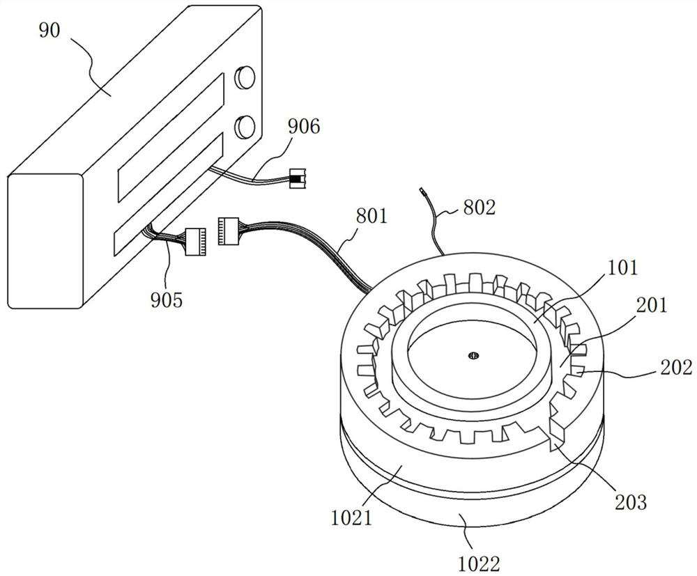
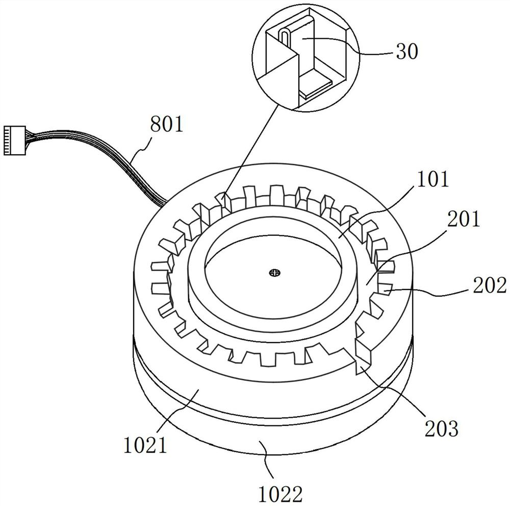
The invention relates to the technical field of electronic wire harness production testing equipment, in particular to a motor power line conduction testing device which comprises a fixing disc, a power supply and a testing disc assembly. The testing disc assembly comprises a disc upper portion, the upper surface of the disc upper portion is provided with a disc-shaped first recess, and the fixing disc is located in the center of the first recess; the inner wall of the first recess and the outer wall of the fixed disc are spaced to form a first groove, and the coil assembly is embedded into the first groove when fixed on the fixed disc; the inner wall of the first recess is provided with at least two second grooves at intervals, the second grooves are uniformly arranged around the first recess, the second grooves are recesses which are vertical to the inner wall of the first recess, any second groove is internally provided with a metal test piece, and any test piece is connected with the low potential of the power supply; the number of the low-potential terminals of the power supply is not less than the number of the test pieces, and any test piece is connected with the low potential of the power supply through an indication unit. The operation precision is improved, the testing efficiency is improved, and repeated labor is reduced.

Description

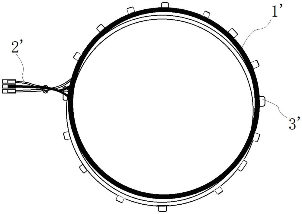
technical field [0001] The invention relates to the technical field of electronic wiring harness production testing equipment, in particular to a motor power line continuity testing device. Background technique [0002] In order to meet the needs of modular design and manufacture, some motors (motors) on the market use the power cord part to be independently made into a coil group structure, so that it can be manufactured separately from the stator coil winding, and then assembled and connected in subsequent production. For motors with this type of structure, the shape of the power cord is generally designed to match the ring shape of the stator. During production, two or three strands of the power cord are wound into a ring shape, and then the lead wires of each strand are drawn from the same position. After being drawn out, bundled in bundles (such as image 3 structure marked 2' in ). Each of these strands corresponds to several groups of coils in the coil winding that a...

Claims


Application Information

Patent Timeline
Patent Type & Authority Applications(China)
IPC IPC(8): G01R31/72G01R31/66
CPCG01R31/72G01R31/66
Inventor 方国权徐刚
Owner 达晟(上海)电子有限公司
Why Eureka
Try Eureka