
Energy spectrum-dose measuring method and device

A measurement method and energy spectrum technology, applied in the field of radiation energy spectrum-dose measurement method and device, can solve problems such as complex deconvolution process, complex G function construction, unstable solution results, etc., to improve energy response, Solve the effect of unstable solution results and wide applicability

Pending Publication Date: 2022-07-12
NAT INST OF METROLOGY CHINA
View PDF3 Cites 0 Cited by
  • Summary
  • Abstract
  • Description
  • Claims
  • Application Information

AI Technical Summary

Problems solved by technology

In the process of use, there are complex construction of G function, complicated deconvolution process, and problems such as unstable solution results and non-convergence, so there are certain difficulties in application.

Method used


Image

  • Energy spectrum-dose measuring method and device
  • Energy spectrum-dose measuring method and device
  • Energy spectrum-dose measuring method and device

Examples


Embodiment 1

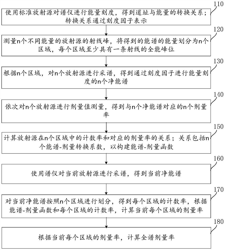
[0054] figure 1 It is one of the schematic flow charts of the energy spectrum-dose measurement method provided in the first embodiment of the present invention; such as figure 1 As shown, this application includes the following steps:

[0055] Step 110, use a standard radioactive source to perform energy calibration on the spectrometer to obtain the conversion relationship between the track and energy; the conversion relationship is represented by a scale factor;

[0056] Among them, the all-energy peak position of the standard radiation source can be corresponded to the channel address of the energy spectrum, and the conversion relationship between the channel address and the energy can be obtained. During the calibration of the spectrometer, in order to improve the accuracy of the subsequent conversion relationship, no less than five energy points are used for the calibration operation. At each energy point, a set of track addresses and energies can be obtained. The scale fa...

Embodiment 2

[0149] Figure 8 This is a schematic structural diagram of the energy spectrum-dose measurement device provided in the second embodiment of the present invention. see Figure 8 , the energy spectrum-dose measurement device includes: a spectrometer calibration module 810 , an energy region grouping module 820 , a spectrum collection module 830 , a measurement module 840 , a conversion coefficient solution module 850 and a calculation module 860 .

[0150] The spectrometer calibration module 810 is used to perform energy calibration on the spectrometer using a standard radioactive source to obtain the conversion relationship between the track address and the energy; the conversion relationship is represented by a scale factor;

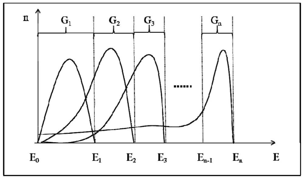
[0151] The energy region grouping module 820 is used to measure the ray peaks of n radioactive sources with different energies, and divide the energy of the obtained energy spectrum into n regions, each region having at least one ray full-energy peak posi...


PUM


Abstract

The invention provides an energy spectrum-dose measuring method and device, and the method comprises the steps: carrying out the energy calibration of a spectrometer through a standard radioactive source, and obtaining a conversion relation between a channel address and energy; the conversion relation is expressed through scale factors; n ray peaks of radioactive sources with different energies are measured, the energy of the obtained energy spectrum is divided into n regions, and each region at least has a full-energy peak position of one ray; according to the n areas, spectrum collection is carried out on the n radioactive sources, and n net energy spectrums subjected to energy calibration through the calibration factors are obtained; performing dose value measurement on the n radioactive sources in sequence to obtain n dose rates corresponding to the n net energy spectrums; calculating the relationship between the counting rate of the radioactive source in the n areas and the corresponding dose rate; the relation comprises n energy spectrum-dose conversion coefficients, so as to construct an energy spectrum-dose function; and calculating the full-spectrum dose rate according to the dose rate of each current region.

Description

technical field [0001] The invention relates to the technical field of data processing, in particular to a method and device for measuring radiation energy spectrum-dose. Background technique [0002] At present, the commonly used gamma radiation dose rate measurement instruments in the field of environmental radiation monitoring include GM counter tubes, high-pressure ionization chambers, semiconductor-based dosimeters, and scintillator-based dosimeters. This type of dosimeter realizes dose (rate) measurement through the linear conversion of radiation counting and dose, but due to inherent reasons such as its structural design, there is a problem of poor energy response. In addition, there are dose rate meters based on X / γ spectrometers, most of which use the energy spectrum-dose conversion method to compensate / correct the energy response. [0003] The energy spectrum-dose conversion method is a method in which the measured energy spectrum is solved by a certain algorithm ...

Claims


Application Information

Patent Timeline
IPC IPC(8): G01T1/02G01T1/36
CPCG01T1/02G01T1/36Y02E30/30
Inventor 黄建微李德红曹蕾张璇张晓乐张耀锋刘川凤张健刘展杨扬
Owner NAT INST OF METROLOGY CHINA
Learn More