
Protective clamping device based on automatic control

A transmission device and clamping device technology, applied in the direction of program control manipulators, chucks, manufacturing tools, etc., can solve the problems of impact force workpiece damage, can not stop work immediately, achieve good clamping, reduce losses, and avoid damage Effect

Pending Publication Date: 2022-07-15
JIANGSU VOCATION & TECHNICAL COLLEGE OF FINANCE & ECONOMICS
View PDF0 Cites 0 Cited by
  • Summary
  • Abstract
  • Description
  • Claims
  • Application Information

AI Technical Summary

Problems solved by technology

[0004] The purpose of the present invention is to provide a protective clamping device based on automatic control to solve the problem that the impact force generated when the mechanical arm performs directional movement is easy to cause damage to the workpiece, and the work cannot be stopped immediately when the workpiece is damaged. Problems where personnel know and cannot stop working immediately to minimize losses

Method used


Image

  • Protective clamping device based on automatic control
  • Protective clamping device based on automatic control
  • Protective clamping device based on automatic control

Examples


Embodiment Construction

[0030] The technical solutions in the embodiments of the present invention will be clearly and completely described below with reference to the accompanying drawings in the embodiments of the present invention. Obviously, the described embodiments are only a part of the embodiments of the present invention, but not all of the embodiments. Based on the embodiments of the present invention, all other embodiments obtained by those of ordinary skill in the art without creative efforts shall fall within the protection scope of the present invention.

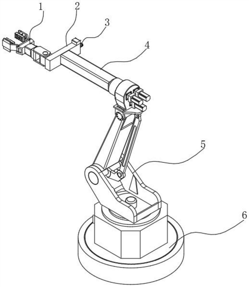
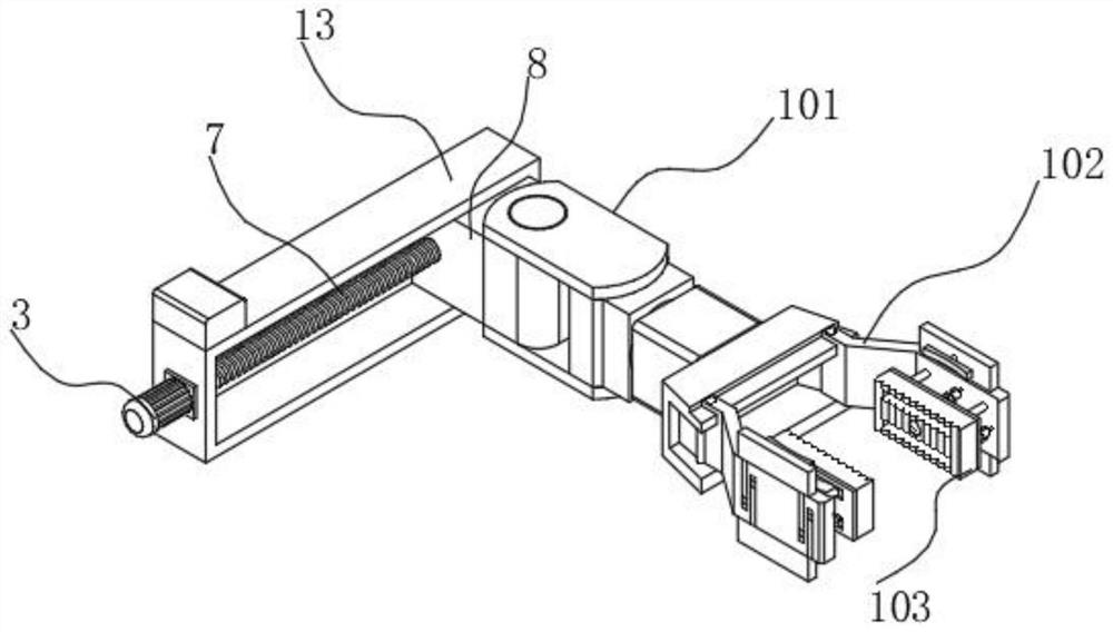
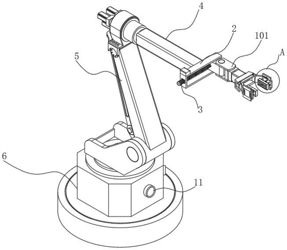
[0031] The present invention provides such as Figure 1-8 A kind of protective type gripping device based on automatic control shown in, comprises base 6, base 6 is provided with central processing unit 9 inside, the top of base 6 is fixedly provided with transmission device 5, and the top of transmission device 5 is provided with rotating device 4, One end of the rotating device 4 away from the transmission device 5 is provided with ...


PUM


Abstract

The protective clamping device based on automatic control comprises a base, a central processor is arranged in the base, a transmission device is fixedly arranged at the top of the base, a rotating device is arranged at the top of the transmission device, and a synchronous assembly is arranged at the end, away from the transmission device, of the rotating device. A clamping mechanism is movably arranged on the synchronous assembly, the clamping mechanism comprises a clamping device arranged on the synchronous assembly, clamping arms are arranged on the two sides of the end, away from the synchronous assembly, of the clamping device in a transmission mode, and pressure pre-detection mechanisms are fixedly arranged on the inner sides of the clamping arms; in the whole process, the pressure detection mechanism is used for evaluating the clamping force, damage of impact force to the workpiece is avoided, then the pressure can be well controlled through detection of the displacement sensor, workpiece deformation monitoring can be achieved, workers can be informed in the first time, and operation of all equipment is stopped to reduce losses.

Description

technical field [0001] The invention belongs to the field of gripping equipment, in particular to a protective gripping device based on automatic control. Background technique [0002] A manipulator is an automatic operation device that can imitate some action functions of a human arm to grab, carry objects or operate tools according to a fixed program. The manipulator is the earliest industrial robot and the earliest modern robot. It can replace the heavy labor of humans to realize the mechanization and automation of production, and can operate in harmful environments, so it is widely used in machinery manufacturing, metallurgy, electronics, light engineering and atomic energy. Among them, the gripping manipulator generates power by electric or pneumatic means to replace frequent manual grasping actions, which reduces the work intensity of personnel to a certain extent. [0003] When the gripping equipment grips the workpiece on the assembly line, since the gripping equip...

Claims


Application Information

Patent Timeline
Patent Type & Authority Applications(China)
IPC IPC(8): B25J9/04B25J15/00B25J15/08B25J19/02
CPCB25J9/04B25J15/08B25J15/0028B25J19/021
Inventor 赵林林武涛刘军
Owner JIANGSU VOCATION & TECHNICAL COLLEGE OF FINANCE & ECONOMICS
Learn More