
Portal frame workpiece taking and spraying robot

A gantry and robot technology, applied in the field of robotics, can solve the problems of the load weight not meeting the requirements, the heavy load robot is bulky, and the load can be small, etc., to achieve a wide range of motion, improve machine performance, and reduce load. Effect

Pending Publication Date: 2022-07-15
BENGBU COLLEGE +1
View PDF12 Cites 0 Cited by
  • Summary
  • Abstract
  • Description
  • Claims
  • Application Information

AI Technical Summary

Problems solved by technology

However, the robots currently on the market (such as the automatic cutting and welding device for automotive B-pillar trims disclosed by the authorized announcement number CN105935840B include gantry-based robots) also generally have some problems, including: heavy-duty robots are bulky and inefficient , difficult maintenance, poor security, etc.
However, the small load robot can carry a small load, and the load weight cannot meet the use requirements in some applications.

Method used


Image

  • Portal frame workpiece taking and spraying robot
  • Portal frame workpiece taking and spraying robot
  • Portal frame workpiece taking and spraying robot

Examples


Embodiment

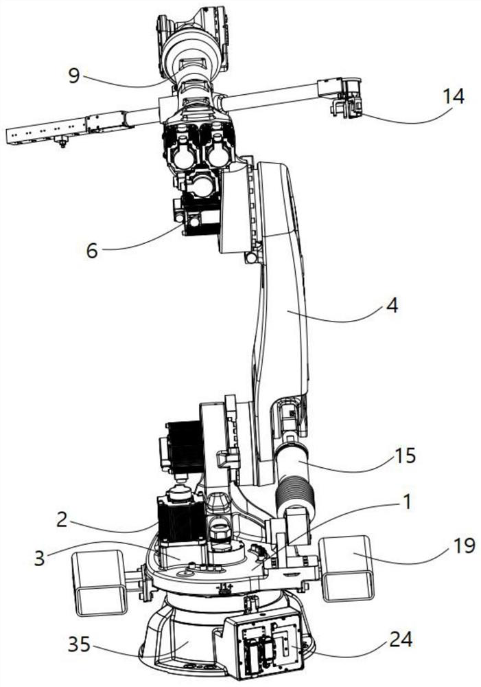
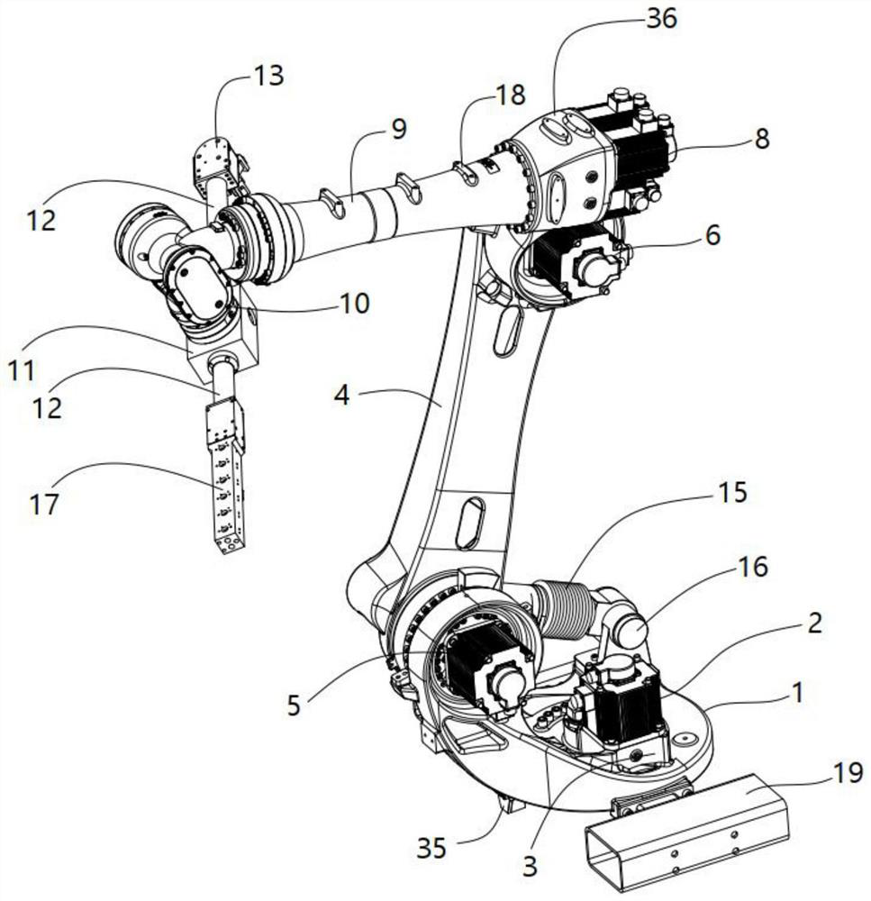
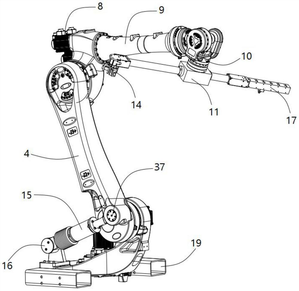
[0036] see Figure 1 to Figure 6 , the present invention provides a kind of technical scheme:

[0037] A gantry pick-up spray robot, comprising:

[0038] The base 35 is installed with the rotatable chassis 1;

[0039] The first driving device 2 is installed on the chassis 1 by the installation transmission mechanism 3, and is used to drive the chassis 1 to rotate relative to the base 35;

[0040] One end of the swing arm 4 is mounted on the chassis 1, and is driven by the second driving device 5 on the chassis 1 to rotate up and down relative to the chassis 1 in space;

[0041] The third driving device 6 is installed on the other end of the swing arm 4, and is used to rotate up and down in space with the swing arm 4;

[0042] a fourth driving device 8, mounted on the third driving device 6;

[0043] One end of the rotating arm 9 is installed with the fourth driving device 8, and is driven by the fourth driving device 8 to rotate left and right relative to the third driving...


PUM


Abstract

The invention provides a portal frame part taking and spraying robot. The portal frame part taking and spraying robot is characterized in that a base is provided with a rotatable chassis; the first driving device is mounted on the chassis through a mounting transmission mechanism and is used for driving the chassis to rotate relative to the base; one end of the swing arm is mounted on the chassis and is driven by a second driving device on the chassis to rotate up and down relative to the chassis in the space; the third driving device is installed at the other end of the swing arm and used for rotating up and down in the space with the swing arm. The fourth driving device is mounted on the third driving device; one end of the rotating arm is mounted on the fourth driving device and is driven by the fourth driving device to rotate leftwards and rightwards relative to the third driving device in the space; and the paws are mounted and fixed with the bearing blocks through the claw rods. According to the robot, manpower can be replaced to achieve large-load carrying, clamping and spraying, and meanwhile some defects, such as insufficient rigidity, complex structure, limited bearing and the like, of the robot in the current market are greatly overcome.

Description

technical field [0001] The invention relates to the technical field of robots, in particular to a gantry rack picking and spraying robot. Background technique [0002] The robot device is a model that simulates the manipulator around the automation equipment in the industrial production process, and it can automatically complete the required actions according to the given program and requirements. However, the robots currently used in the market (such as the automatic B-pillar interior cutting and welding device disclosed in Authorized Announcement No. CN105935840B, including gantry-based robots) also generally have some problems, including: heavy-duty robots are bulky and inefficient. , maintenance difficulties, poor security, etc. On the other hand, small-load robots can carry small loads, and in some applications, the load weight cannot meet the requirements for use. SUMMARY OF THE INVENTION [0003] The purpose of the present invention is to provide a gantry pick-up ...

Claims


Application Information

Patent Timeline
Patent Type & Authority Applications(China)
IPC IPC(8): B25J11/00B25J15/08B25J18/02
CPCB25J11/00B25J15/08B25J18/025
Inventor 李现伟陈国龙周芮冬
Owner BENGBU COLLEGE
Learn More