Yarn breakage automatic stop system of double-control type ring spinning machine

A ring spinning machine, end-break automatic stop technology, applied in spinning machines, continuous winding spinning machines, textiles and papermaking, etc., can solve the problem of uneven thickness of finished yarns, to save sliding distance, The effect of increasing the rotation angle

Active Publication Date: 2022-07-15
PINTER YUHUA CHINA TECH CO LTD
View PDF7 Cites 1 Cited by
  • Summary
  • Abstract
  • Description
  • Claims
  • Application Information

AI Technical Summary

Problems solved by technology

[0005] The object to be realized by the present invention is to provide a yarn breakage automatic stop system to solve the problem that the rear roller stops rotating, while the front roller and middle roller continue to rotate, and the yarn remaining between the front roller, middle roller and rear roller The thread, and the yarn between the front roller and the winding roller are stretched and thinned, and enter the winding roller to be wound into the finished yarn, resulting in the technical problem of uneven thickness of the finished yarn

Method used


Image

  • Yarn breakage automatic stop system of double-control type ring spinning machine
  • Yarn breakage automatic stop system of double-control type ring spinning machine
  • Yarn breakage automatic stop system of double-control type ring spinning machine

Examples


specific Embodiment

[0032] In the description of the present invention, it should be understood that the terms "center", "longitudinal", "lateral", "length", "width", "thickness", "upper", "lower", "front", " Rear, Left, Right, Vertical, Horizontal, Top, Bottom, Inner, Outer, Clockwise, Counterclockwise, Axial, The orientations or positional relationships indicated by "radial direction", "circumferential direction", etc. are based on the orientations or positional relationships shown in the accompanying drawings, which are only for the convenience of describing the present invention and simplifying the description, rather than indicating or implying the indicated devices or elements. It must have a specific orientation, be constructed and operate in a specific orientation, and therefore should not be construed as a limitation of the present invention.

[0033] In order to make the objectives, technical solutions and advantages of the present invention clearer, the present invention will be furthe...

Embodiment 1

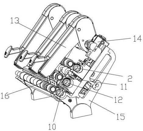
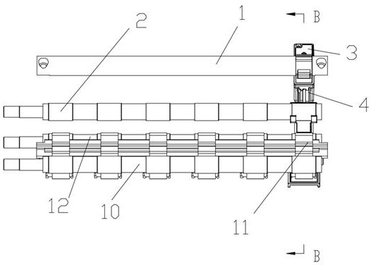
[0036] like figure 1 Shown: a group of rollers are fixed on the frame 15 of the ring spinning frame, including the front roller 10, the middle roller 12 and the back roller 2, the front roller 10, the middle roller 12 and the back roller 2 are fixed above the head assembly 13 , the bottom of the indenter assembly 13 is provided with the front roller 10, the top of the middle roller 12 and the rear roller 2 is fixed with a press roller corresponding to the indenter assembly 13, the middle roller 12 is provided with a lower belt 10, corresponding to the middle roller There is an upper belt 16 on the pressing roller, and the yarn passes between the pressing roller and the roller. At the middle roller, the yarn passes through the direct contact surface of the lower belt 10 and the upper belt 16; the upper part of the frame 15 is fixed with a drive Component 3, such as figure 2 As shown, the drive assembly 3 is connected with a push plate 4, the push plate 4 is provided with a nu...

Embodiment 2

[0045] like Figure 5 As shown, on the basis of Embodiment 1, the drive assembly 3 is connected with a push plate 4, and the push plate 4 is provided with a number of rectangular grooves arranged in a straight line. The first support plate 6 and the second support plate 9 are connected, the upper end of the first support plate 6 is hinged with the first arc wedge 5 through the first hinge point 801, and the second support plate 9 is hinged with the first hinge point 8. The second arc-shaped wedge 7 and the first arc-shaped wedge 5 are clipped on the back roller, and the second arc-shaped wedge is clipped on the middle roller and located under the lower belt 10 .

[0046] The specific use method is the same as that of the first embodiment, and will not be repeated here. The difference is that the second embodiment, as shown in Image 6 As shown, since the arc-shaped wedge and the support plate are connected in a hinged manner, the limit positions of the first support plate 6 a...


PUM


Abstract

The invention discloses a double-control type ring spinning machine yarn broken end automatic stop system, an automatic stop device and a control device, the control device controls the automatic stop device to cut off transmission contact between yarn and rollers, the rollers comprise a front roller, a middle roller and a rear roller, the automatic stop device comprises a push plate sliding in a fixed sliding way, and the push plate is connected with the middle roller and the rear roller. The push plate is connected with a supporting plate in a sliding mode, the top of the supporting plate is hinged to an arc-shaped wedge, the arc-shaped wedge is arranged on the roller in a sleeved mode, and the push plate, the supporting plate and the wedge form a double-swing-rod sliding block mechanism or a three-swing-rod sliding block mechanism with the roller as a fulcrum. The device has the beneficial effects that the supporting plate slides and is hinged to the arc-shaped wedge, so that the rotating angle of the arc-shaped wedge on the rollers is increased, the middle roller and the rear roller are stopped at the same time, or the front roller, the middle roller and the rear roller are stopped at the same time, and the situation that the yarn between the rear rollers is stretched and thinned after the yarn is broken is avoided.

Description

technical field [0001] The invention belongs to the technical field of ring spinning frame self-stop after yarn breakage, and in particular relates to a double-control type ring spinning frame yarn breakage self-stop system. Background technique [0002] When the traditional ring spinning frame is working, yarn breakage often occurs. There are many kinds of yarn breakage detection technologies in the existing technology, which can detect the yarn breakage in time and issue an alarm, and then notify the yarn breaker to the operator. bits are processed. After the end is broken, the broken spun yarn is easily wound on the rollers, belts and aprons in the drafting mechanism of the ring spinning frame, causing damage to the machine parts. At the same time, the spun yarn is continuously sucked by the flute tube, which wastes raw materials. Among them: [0003] Chinese utility model patent CN200520045861.8 discloses a roving self-stop feeding device for spun yarn broken ends. The ...

Claims


Application Information

Patent Timeline
Patent Type & Authority Applications(China)
IPC IPC(8): D01H13/16D01H1/22
CPCD01H13/16D01H1/22Y02W30/66
Inventor 刘文田崔杰张永龙刘晓洁
Owner PINTER YUHUA CHINA TECH CO LTD
Why Eureka
Try Eureka