Drying device for mechanical equipment machining

A technology of drying device and mechanical equipment, applied in drying, drying machine, drying gas arrangement and other directions, can solve the problems of slow drying of parts, failure of parts to be put into use in time, and reduction of processing efficiency of mechanical equipment, etc. Achieve the effect of increasing drying speed, practical device and improving processing efficiency

Active Publication Date: 2022-07-15
江苏瀚高科技有限公司
View PDF8 Cites 0 Cited by
  • Summary
  • Abstract
  • Description
  • Claims
  • Application Information

AI Technical Summary

Problems solved by technology

[0003] The purpose of the present invention is to solve the following shortcomings in the prior art. Since the current drying device can only blow hot air to dry a certain fixed surface of the parts, the drying speed of other surfaces of the parts is relatively slow, which is not conducive to the drying of the parts. The complete drying of the parts is slow, resulting in the parts not being put into use in time, thereby reducing the processing efficiency of mechanical equipment, and a drying device for mechanical equipment processing is proposed

Method used


Image

  • Drying device for mechanical equipment machining
  • Drying device for mechanical equipment machining
  • Drying device for mechanical equipment machining

Examples


Embodiment Construction

[0021] The technical solutions in the embodiments of the present invention will be clearly and completely described below with reference to the accompanying drawings in the embodiments of the present invention. Obviously, the described embodiments are only a part of the embodiments of the present invention, rather than all the embodiments.

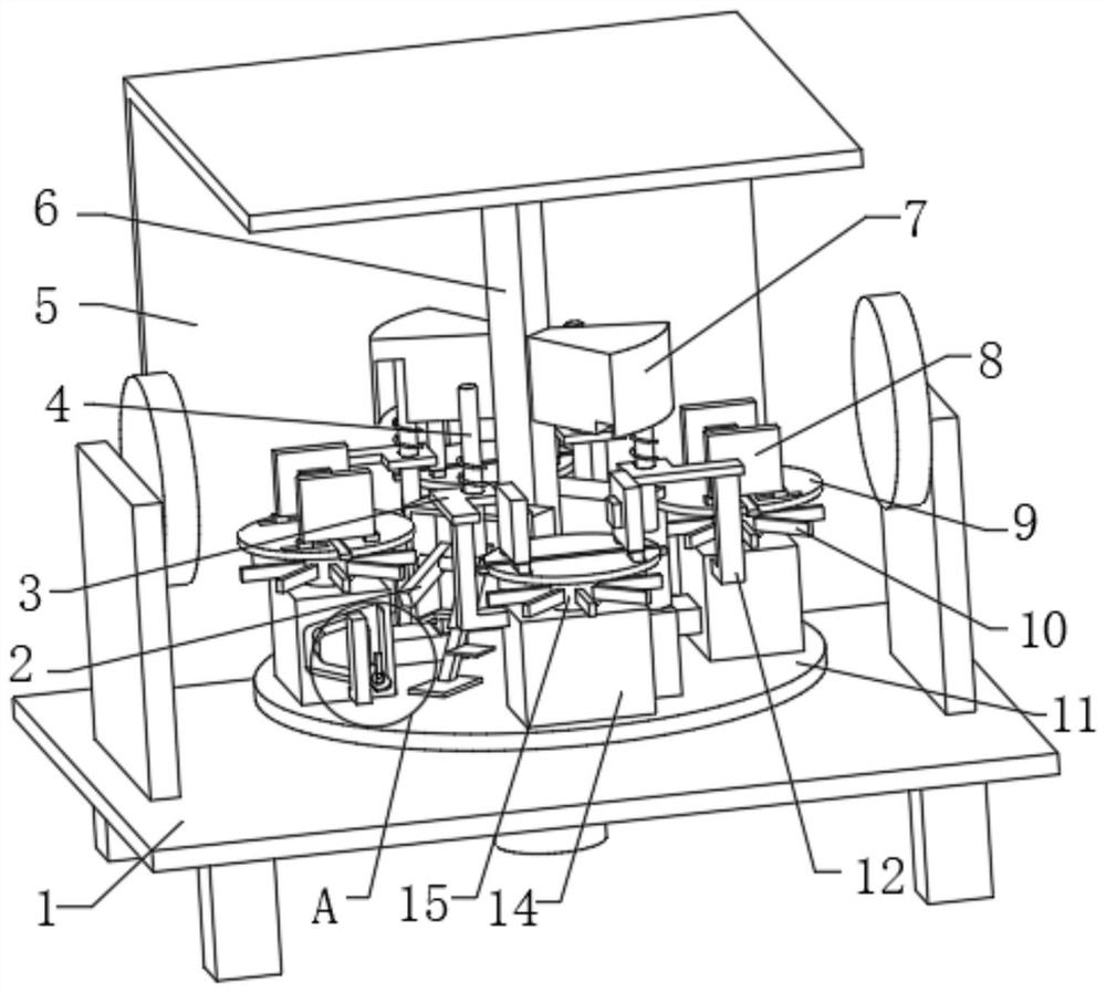
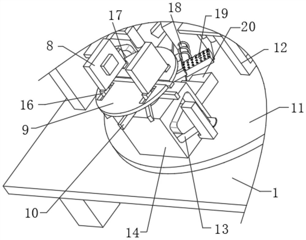
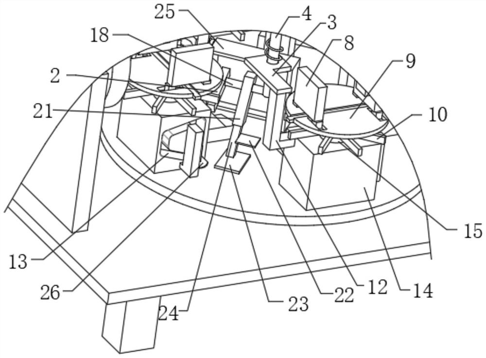
[0022] refer to Figure 1-6 , a drying device for mechanical equipment processing, the drying device for mechanical equipment processing includes: a base 1 and two hot air blowers, the base 1 is connected with a support plate 11 through a rotating shaft, and a plurality of mounting blocks are fixedly arranged on the support plate 11 14. Each mounting block 14 is rotatably provided with a support column 15, the first hinge plate 9 and the second hinge plate are hinged on the support column 15, and a plurality of rectangular blocks 10 are fixedly connected to the support column 15. The hinge plate 9 is provided with two splints 8; the fixed ...


PUM


Abstract

The invention discloses a drying device for mechanical equipment machining, the drying device for mechanical equipment machining comprises a base and two hot air blowers, the base is connected with a supporting plate through a rotating shaft, a plurality of mounting blocks are fixedly arranged on the supporting plate, a supporting column is rotatably arranged on each mounting block, and the supporting columns are fixedly arranged on the base. A first hinge plate and a second hinge plate are hinged to the supporting column, a plurality of rectangular blocks are fixedly connected to the supporting column, and two clamping plates are arranged on each first hinge plate; the device comprises a fixing plate and a mounting column, two shells are fixedly arranged on the mounting column, and each shell is connected with a rotating rod through a torsion spring. According to the part drying device, the drying speed of other surfaces of parts is increased, complete drying of the parts is better facilitated, the complete drying speed of the parts can be greatly increased, the parts can be put into use in time, and therefore the machining efficiency of mechanical equipment is improved.

Description

technical field [0001] The invention relates to the technical field of mechanical equipment, in particular to a drying device for processing mechanical equipment. Background technique [0002] With the continuous development of society, the types and functions of mechanical equipment are becoming more and more diverse. In the process of production and processing, each complete mechanical equipment needs to be assembled with a variety of mechanical parts. Before some mechanical parts are used, It needs to be cleaned. In order to improve the drying speed of the parts, a drying device is usually used to dry them. However, because the current drying device can only dry a certain fixed surface of the parts with hot air, other surfaces of the parts are caused. The drying speed of the parts is slow, which is not conducive to the complete drying of the parts. The complete drying speed of the parts is slow, so that the parts cannot be put into use in time, thus reducing the processin...

Claims


Application Information

Patent Timeline
Patent Type & Authority Applications(China)
IPC IPC(8): F26B11/18F26B25/18F26B21/00
CPCF26B11/18F26B25/18F26B21/004Y02P70/10
Inventor 王红军
Owner 江苏瀚高科技有限公司
Why Eureka
Try Eureka