
System and method for achieving uniformity of substrate processing using transformer

A transformer and voltage technology, applied in the direction of discharge tubes, electrical components, multi-terminal pair networks, etc., can solve the problem of the uniformity of the processing rate decreasing, and achieve the effect of improving the uniformity

Pending Publication Date: 2022-07-15
LAM RES CORP
View PDF0 Cites 0 Cited by
  • Summary
  • Abstract
  • Description
  • Claims
  • Application Information

AI Technical Summary

Problems solved by technology

In addition, the uniformity of processing rate across each wafer is reduced

Method used


Image

  • System and method for achieving uniformity of substrate processing using transformer
  • System and method for achieving uniformity of substrate processing using transformer
  • System and method for achieving uniformity of substrate processing using transformer

Examples


Embodiment Construction

[0037] The following embodiments describe systems and methods for using transformers to achieve uniformity of processed substrates. It will be apparent that the embodiments herein may be practiced without some or all of these specific details. In other instances, well-known processing operations have not been described in detail in order not to unnecessarily obscure the embodiments herein.

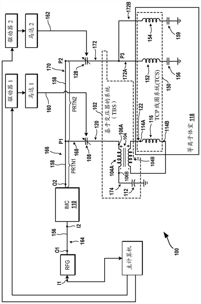
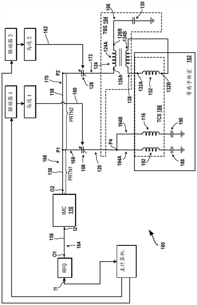
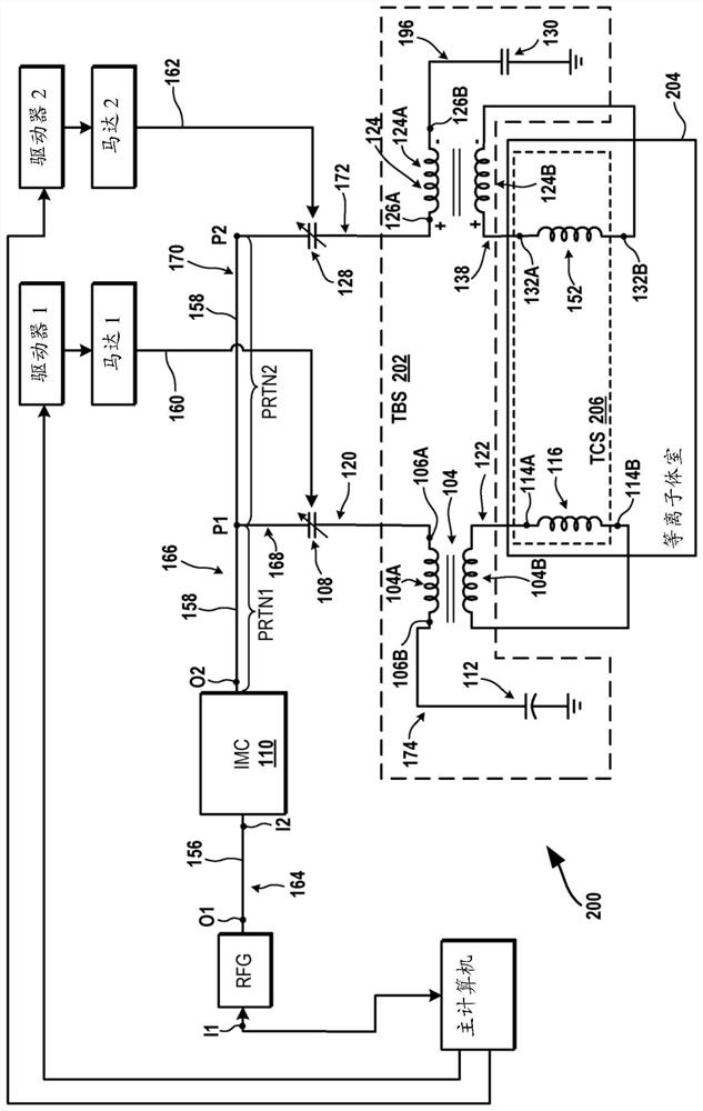
[0038]FIG. 1A is a schematic diagram of an embodiment of a system 100 for illustrating the use of a transformer based system (TBS) 102 for internal coils of a transformer coupled plasma (TCP) chamber 118 . In this document, the TBS is sometimes referred to as a transformer device. System 100 includes a host computer, radio frequency generator (RFG), impedance matching circuit (IMC) 110 , driver 1 , motor 1 , driver 2 , motor 2 , connection mechanism 160 , and connection mechanism 162 . System 100 also includes TBS 102 and plasma chamber 118 . The system 100 also includes a variable capa...


PUM


Abstract

Systems and methods for using a transformer to achieve uniformity in substrate processing are described. One of the systems includes a primary winding having a first end and a second end. The first end is coupled to an output of an impedance matching circuit, and the second end is coupled to a capacitor. The system also includes a secondary winding associated with the primary winding, and the secondary winding is coupled to a first end and a second end of a transformer coupled plasma (TCP) coil of the plasma chamber. The primary winding receives a modified radio frequency (RF) signal from the impedance matching circuit to generate a magnetic flux to induce a voltage in the secondary winding. An RF signal generated by the voltage is transmitted from the secondary winding to the TCP coil.

Description

technical field [0001] Embodiments described in this disclosure relate to systems and methods that use transformers to achieve uniformity in substrate processing. Background technique [0002] The background description provided herein is for the purpose of generally presenting the context of the disclosure. The work of the presently named inventors is neither expressly nor implicitly acknowledged as prior art to the present disclosure to the extent that it is described in this Background section and in aspects of the specification that were not identified as prior art at the time of filing the application. technology. [0003] In a plasma tool, one or more radio frequency (RF) generators are coupled to an impedance matching network. The impedance matching network is coupled to the plasma chamber. An RF signal is supplied to the impedance matching network from an RF generator. The impedance matching network outputs the RF signal after receiving the RF signal. The RF sig...

Claims


Application Information

Patent Timeline
Patent Type & Authority Applications(China)
IPC IPC(8): H01J37/32H03H7/40
CPCH01J37/32174H01J37/32183H01J37/321H03H7/38H01J2237/3321H01J2237/334H01F27/28H01J37/32091H01J2237/327
Inventor 苏尼尔·卡普尔丹·马罗尔彭迅
Owner LAM RES CORP
Learn More