
Display driving circuit system

A technology of display drive and circuit system, applied in static indicators, instruments, etc., to achieve the effect of reducing costs

Pending Publication Date: 2022-07-19
FOCALTECH ELECTRONICS
View PDF0 Cites 0 Cited by
  • Summary
  • Abstract
  • Description
  • Claims
  • Application Information

AI Technical Summary

Problems solved by technology

The flexible circuit board is electrically connected to the display panel

Method used


Image

  • Display driving circuit system
  • Display driving circuit system
  • Display driving circuit system

Examples


Embodiment Construction

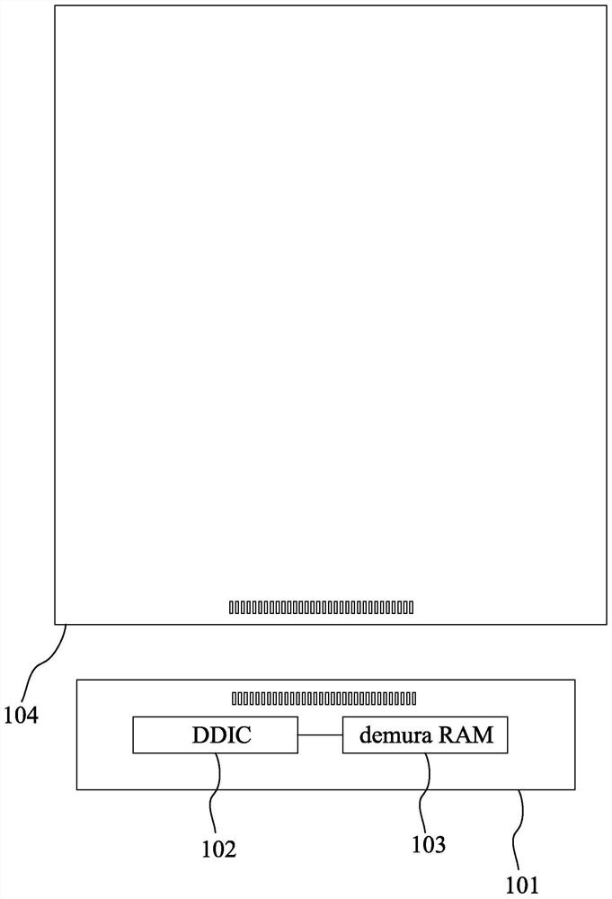
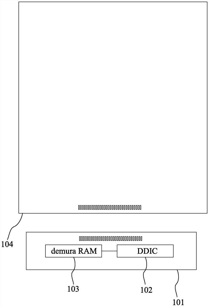
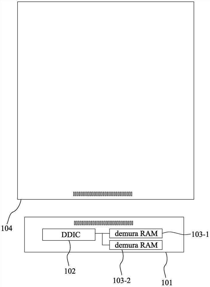
[0036] figure 1 It is a schematic diagram of a display driving circuit system according to a preferred embodiment of the present invention. Please refer to figure 1 , the display driving circuit system includes a flexible circuit board (FPC) 101 , a display driving integrated circuit (DDIC) 102 and a brightness compensation memory (demura RAM) 103 . The flexible circuit board 101 is used to electrically connect the display panel 104 . According to the needs of the process, the display driver integrated circuit 102 and the brightness compensation memory 103 are all disposed on the flexible circuit board 101 . And in this embodiment, the brightness compensation memory 103 is arranged on the right side of the display driving integrated circuit 102 . Generally speaking, the shape of the display driving integrated circuit 102 may be a rectangle or a rectangle.

[0037] The main function of the brightness compensation memory 103 is to correct and compensate the display of the pa...


PUM


Abstract

The invention provides a display driving circuit system. The display driving circuit system comprises a flexible circuit board, a brightness compensation memory (emura RAM) and a display driving integrated circuit. The flexible circuit board is electrically connected with the display panel. The brightness compensation memory is configured on the flexible circuit board. The display driving integrated circuit is arranged on the flexible circuit board and is provided with a rectangular structure, a first side of the display driving integrated circuit is electrically connected with the brightness compensation memory, the first side is a short side of the rectangular structure of the display driving integrated circuit, and the brightness compensation memory is arranged on the first side of the display driving integrated circuit.

Description

technical field [0001] The present invention relates to a technology of a display driving integrated circuit. More specifically, the present invention relates to a display driving circuit system with an external memory for storing brightness compensation data. Background technique [0002] Organic light-emitting diodes, as a current-mode light-emitting device, have been increasingly used in high-performance displays. Due to its self-luminous properties, compared with liquid crystal display panels, active matrix organic light emitting diodes (AMOLEDs) have many advantages such as high contrast ratio, ultra-thinness, and flexibility. However, brightness uniformity is still one of the main problems it is currently facing. To solve this problem, in addition to process improvement, brightness compensation technology has to be mentioned. [0003] The compensation method of brightness uniformity (Demura) generally uses external compensation. External compensation refers to the met...

Claims


Application Information

Patent Timeline
Patent Type & Authority Applications(China)
IPC IPC(8): G09G3/3208G09G3/3225
CPCG09G3/3208G09G3/3225G09G2320/0626
Inventor 潘亨霖许承容蔡曦彦
Owner FOCALTECH ELECTRONICS
Learn More