Laser welding device and welding process for engine control module
A control module and laser welding technology, which is applied to laser welding equipment, welding equipment, manufacturing tools, etc., can solve the problems of reducing workers' work efficiency, wasting workers' time, affecting production efficiency, etc., so as to reduce the cost of construction, avoid collisions, improve The effect of work efficiency
- Summary
- Abstract
- Description
- Claims
- Application Information
AI Technical Summary
Problems solved by technology
Method used
Image

Examples
Embodiment 1
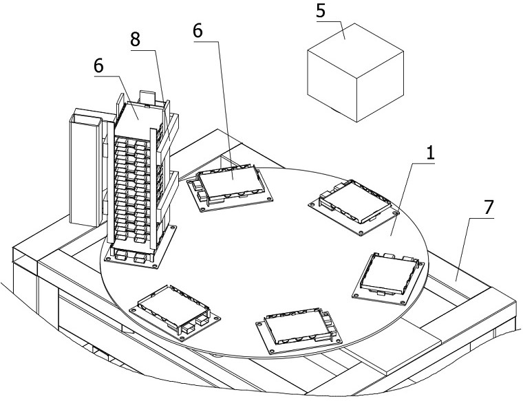
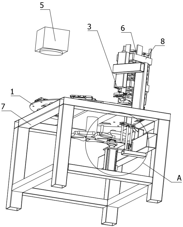
[0048] refer to Figure 1 to Figure 3 The shown laser welding device for an engine control module includes a laser welding machine. The laser welding machine is provided with a laser welding end 5 for laser welding the control module 6. This embodiment also includes a rotating seat 1, a rotating driver 2, One-way clamping mechanism 3 , module push-up mechanism 4 , support frame 7 and material guide frame 8 .
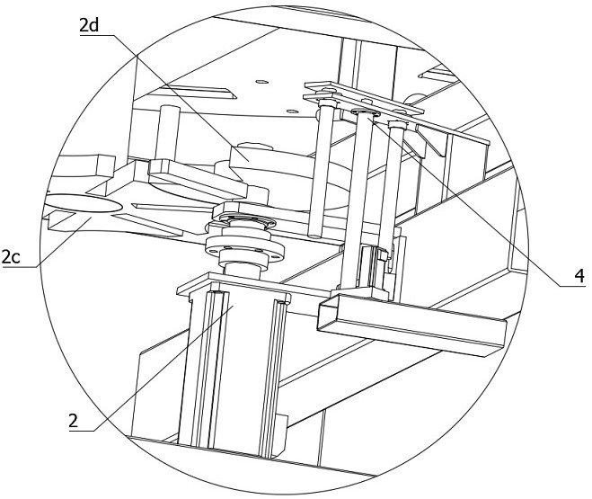
[0049] The swivel base 1 is installed on the table surface of the support frame 7, and is used to drive the control module 6 (the product to be welded / engine control module) placed on the swivel base 1 to rotate. Locator for placement. The rotary driver 2 is used to drive the rotary base 1 to drive the control module 6 to rotate, and the material guide frame 8 is used to store the control module 6 after the welding is completed.
[0050] The module push-up mechanism 4 is used to push the control module 6 on the rotating base 1 to move upwards, so that the control modul...
Embodiment 1
[0055] For the first embodiment, this embodiment further proposes an improved solution, which is different from the first embodiment in that, as Figure 9 As shown, the push-up driver includes an installation circular plate 4f, a push ring 4h and a contact column 4j, the installation circular plate 4f is fixedly installed on the top of the rotating shaft 2b, the push ring 4h is fixedly installed on the installation circular plate 4f, and the contact column 4j is connected by connecting The plate is fixedly connected to the push-up plate 4e, and the outer edge of the contact column 4j is in contact with the top of the push-ring 4h. The push-ring 4h includes a flat bottom section 4h1, a rising section 4h2, a flat top section 4h3 and a sliding section 4h4. The ascending section 4h2 is used to push the contact column 4j upwards when rotating, and the descending section 4h4 is used for contacting and sliding the contact column 4j when rotating. When the rotating shaft 2b rotates, t...
Embodiment 3
[0064] Compared with the first two embodiments, this embodiment further proposes an improved solution, which is different from the second embodiment in that, such as Figure 10 As shown, the tops of both the ascending section 4h2 and the descending section 4h4 are provided with a deceleration section 4h5. By setting the deceleration section 4h5, the control module 6 can be decelerated when the one-way clamping mechanism 3 is clamped, so as to avoid violent collision between the one-way clamping mechanism 3 and the control module 6 during the clamping, which may damage the In the control module 6, when the magnet piece 4b is separated from the control module 6, the separation speed of the magnet piece 4b and the control module 6 is slowed down, so as to prevent the magnet piece 4b from pulling the bottom of the control module 6 into depression due to rapid separation.
PUM
 Abstract
Description
Claims
Application Information
 - R&D
- Intellectual Property
- Life Sciences
- Materials
- Tech Scout
- Unparalleled Data Quality
- Higher Quality Content
- 60% Fewer Hallucinations
Browse by: Latest US Patents, China's latest patents, Technical Efficacy Thesaurus, Application Domain, Technology Topic, Popular Technical Reports.
© 2025 PatSnap. All rights reserved.Legal|Privacy policy|Modern Slavery Act Transparency Statement|Sitemap|About US| Contact US: help@patsnap.com