Tubular casting cooling and grinding device

A casting and tubular technology, which is applied in the field of tubular casting cooling and grinding devices, can solve the problems of low grinding efficiency and low efficiency, and achieve the effect of enhancing the grinding effect

Active Publication Date: 2022-07-22
梅州华和精密工业有限公司
View PDF16 Cites 0 Cited by
  • Summary
  • Abstract
  • Description
  • Claims
  • Application Information

AI Technical Summary

Problems solved by technology

[0003]The cooling and grinding of castings is an important part of casting processing, which is related to the quality of castings. The efficiency of traditional grinding methods is low, especially for some specific shapes of castings , the grinding efficiency is lower, such as pipe castings, and the waste debris produced during grinding is easily absorbed on the inner wall of the pipe during the grinding process, which affects the quality of grinding

Method used


Image

  • Tubular casting cooling and grinding device
  • Tubular casting cooling and grinding device
  • Tubular casting cooling and grinding device

Examples


Embodiment 1

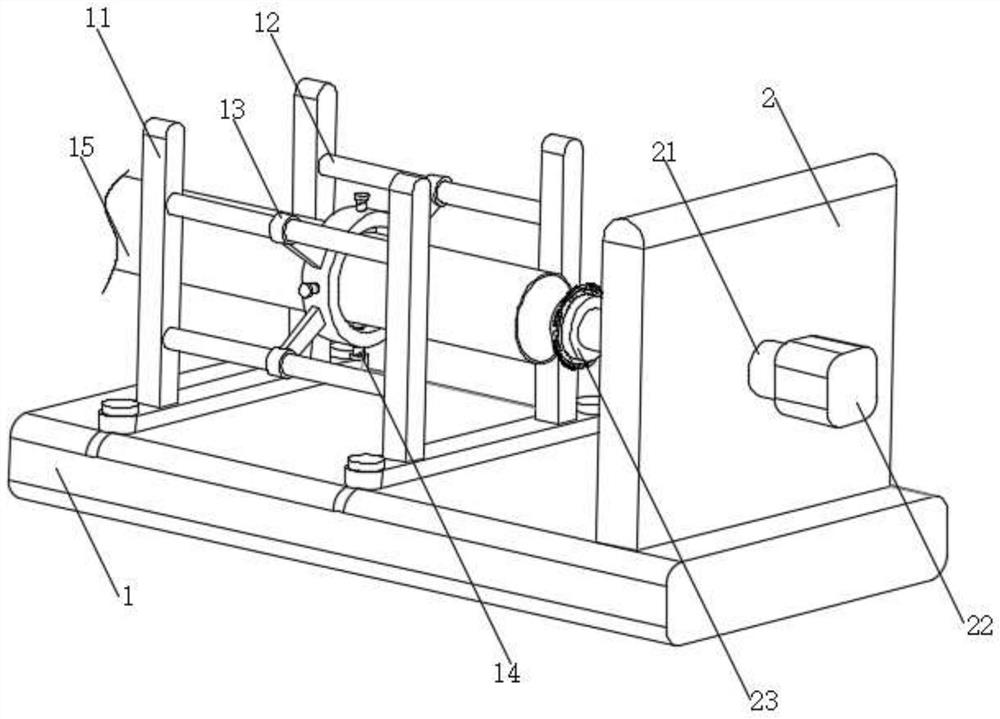
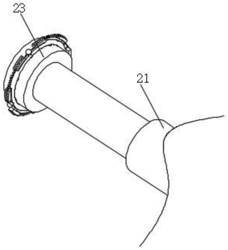
[0027] see Figure 1-Figure 3 As shown, the present invention is a tubular casting cooling and grinding device, including a base 1. The purpose of this setting is to facilitate the support of the entire device. Two support brackets 11 are provided on the left side of the top of the base 1. The purpose of this setting is to In order to facilitate the auxiliary setting of the crossbar 12, the upper and lower sides between the two support frames 11 are respectively fixedly connected with the crossbar 12. The purpose of this setting is to facilitate the auxiliary setting of the clamping ring 13, and the transverse rod 12 is provided with a clamping ring 13. The purpose of this setting is to facilitate the clamping of the pipe body 15, and a number of clamping bolts 14 are provided on the clamping ring 13. The purpose of this setting is to facilitate the fixing of the pipe body 15. Several clamping bolts 14 are threaded. Passing through the outer wall of the clamping ring 13, the p...

Embodiment 2

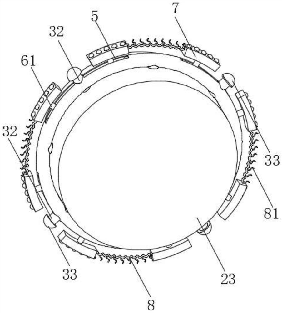
[0035] see Figure 1-Figure 6 As shown, the present invention is a tubular casting cooling and grinding device, including a base 1. The purpose of this setting is to facilitate the support of the entire device. Two support brackets 11 are provided on the left side of the top of the base 1. The purpose of this setting is to In order to facilitate the auxiliary setting of the crossbar 12, the upper and lower sides between the two support frames 11 are respectively fixedly connected with the crossbar 12. The purpose of this setting is to facilitate the auxiliary setting of the clamping ring 13, and the transverse rod 12 is provided with a clamping ring 13. The purpose of this setting is to facilitate the clamping of the pipe body 15, and a number of clamping bolts 14 are provided on the clamping ring 13. The purpose of this setting is to facilitate the fixing of the pipe body 15. Several clamping bolts 14 are threaded. Passing through the outer wall of the clamping ring 13, the p...


PUM


Abstract

The invention discloses a tubular casting cooling and grinding device which comprises a base, two supporting frames are arranged on the left side of the top of the base, cross rods are fixedly connected to the upper side and the lower side between the two supporting frames correspondingly, clamping rings are arranged on the cross rods, and a plurality of clamping bolts are arranged on the clamping rings. And the multiple clamping bolts penetrate through the outer wall of the clamping ring in a threaded mode, a pipe body is arranged in the clamping ring, and a vertical plate is arranged on the right side of the top of the base. According to the tubular casting cooling and grinding device, a worker can clamp and fix a pipe body into a clamping ring through a clamping bolt, a motor is started to drive a telescopic rod to rotate, the telescopic rod adjusts the distance in the rotating process, a grinding disc can extend into the pipe body, a semicircular grinding block can make contact with the inner wall of the pipe body, and therefore the pipe body can be ground conveniently. Therefore, the purpose of polishing the inner wall of the pipe body is achieved.

Description

technical field [0001] The invention relates to the technical field of grinding equipment, in particular to a cooling and grinding device for tubular castings. Background technique [0002] Castings are metal forming objects obtained by various casting methods, that is, the smelted liquid metal is injected into the pre-prepared casting mold by pouring, injection, suction or other casting methods, and after cooling, after grinding and other subsequent processing methods. , The obtained objects with certain shape, size and performance have a long history of application of castings. In modern times, castings occupy a large proportion of mechanical products. [0003] Among them, casting cooling and grinding are an important part of casting processing, which is related to the quality of castings. The traditional grinding method is less efficient, especially for some specific shapes of castings, such as pipe castings, and in the grinding process, the grinding efficiency is lower. ...

Claims


Application Information

Patent Timeline
Patent Type & Authority Applications(China)
IPC IPC(8): B24B5/40B24B55/02B24B41/06B24B55/06B24B47/08B24B41/02
CPCB24B5/40B24B55/02B24B41/067B24B55/06B24B47/08B24B41/02Y02P70/10
Inventor 陈淑娟
Owner 梅州华和精密工业有限公司
Why Eureka
Try Eureka